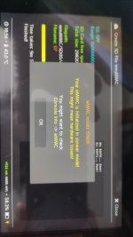
thats his emuemmc partition he need to drop it in the fat 32 partitionBased on the picture, I think your partition is too small. It says you need an additional 12.5 GB of free space.
You are using an out of date browser. It may not display this or other websites correctly.
You should upgrade or use an alternative browser.
You should upgrade or use an alternative browser.
Staff Posts
Recent threadmarks
sharing files
Important Posts
Recent threadmarks
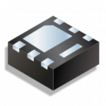
FirmwaresMosfet IRFHS8342TRPBFSomeone who would be so kind as to tell me what mosfet I need, Numbering or model to work the peak without processor cables, that is the only thing that is not clear to me since I already saw what the resistors are and the installation and connection points also already I have them, I only need the connection of the processor to the peak
Attachments
Hello, I created a 12 gb emmc partition on a 128 gb micro sd, and when I try to install some files on it, I get that sign, does anyone know what I should do?
View attachment 364343
You should be copying files into that 12GB partition, obviously based on the picture what ever you try to copy is larger than the space in that partition.
top of this thread under important post fw 2.64please, download link firmware for oled?
Post automatically merged:
only the files he wants on his emmc, atmosphere belongs on the othe fat32 partitionYou should be copying files into that 12GB partition, obviously based on the picture what ever you try to copy is larger than the space in that partition.
Anyone with the cpu flex can tell me what value get the multimeter in continuity mode in the solder points? To check if I have solder mine well. I get 0001 and 0015 in the two points of the two mosfets
You should be good, one pin is GND and the other around 15-20 Ohm (check it on lowest resistance scale).Anyone with the cpu flex can tell me what value get the multimeter in continuity mode in the solder points? To check if I have solder mine well. I get 0001 and 0015 in the two points of the two mosfets
check my post here:I need advice, I have tried to solder the 8342 mosfet and I can't, there must be some way but I can't think of a functional way to do it, I thank you in advance
View attachment 364265
https://gbatemp.net/threads/switch-lite-picofly-blackscreen.630751/#post-10124964
Since no one was able to reply, I did my own tests and I can now tell you all those three points are ground and I was able to boot safely.Oook, I had everything tested but for some reason I decided to reflow everything and OF COURSE I bridges three small caps (those where you pick ground from).
But honestly, they just look like they're on the same trace and I would really love if I could avoid unbridging those little guys and leave everything as is.
Can anyone confirm me this and/or link some proper diagrams?
I'll attach pictures of my mobo and another one I found online with better resolution, for better trace checking
(They're both taken looking from the top of the Switch towards the bottom)
So this is just a reminder that you don't need to panic if you accidentally bridge two or all three of those capacitors to get a gnd connection for the chip
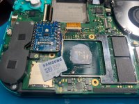
This is how I did it. Make sure you cover it with tape, including it's side edges where the pins are, especially on the left side where the speaker is as the metalic shield may touch the pins on the right side as it slides between the Picofly and the speaker.How did you guys fit The picofly in the lite? I bent the metal shield a little so it barely fits on the right side of the CPU, but I'm worried the pressure might break off the resistors on the RP2040, is it safe or do I need to dremel a hole in the shield?
Post automatically merged:
be sure to check my post here:Alright. I'm about to start on the motherboard. I added pics of what i'm working with for reference.
Few questions:
1) Are the mosfets in my image correct? They say "irh83422tnk". I ordered them because of the "irh8342". I am not familiar with mosfets.
2) If mosfets are correct, should I double them up and follow the "Mariko Dual Mosfet Install Diagram"?
3) My resistors should be good. 47 ohm.
4) Should I be soldering directly to the DAT0, CLK, RST, CMD points on the hac-emmc board OR the ones off the main board? ie: "V1 Patched/V2 Points" diagram
any help is appreciated. i have all the tools and can microsolder pretty well but I am new to the switch.
tia
https://gbatemp.net/threads/switch-lite-picofly-blackscreen.630751/#post-10125262
Attachments
Last edited by KarimPolska,
19,5 Ohm with the lowest resistance. Is a relieve because I had a lot of problem soldering the second mosfet.You should be good, one pin is GND and the other around 15-20 Ohm (check it on lowest resistance scale).
Thank you
Today I made my first erista with pico and cpu flex, I have a 8342 mosfet but it was impossible for me to use it, is there a tutorial using a mosfet or another larger mosfet that is more friendly for soldering?


great, but to weld such a tiny component we need more than photos of a completed installation, if there was a detailed video, for those of us who do not have our technique so refined, it would help us a lot
Today I made my first erista with pico and cpu flex, I have a 8342 mosfet but it was impossible for me to use it, is there a tutorial using a mosfet or another larger mosfet that is more friendly for soldering?
View attachment 364374
great, but to weld such a tiny component we need more than photos of a completed installation, if there was a detailed video, for those of us who do not have our technique so refined, it would help us a lot
View attachment 364389
if u do not have ur "technique" not so refined then microsoldering is nothing for u , then just use flex cables
If you used 470, instead of 47 ohms, you need to change those out.good afternoon colleagues, I installed the rp2040 with 2.64 and when I try to enter the original nand after the first logo it stays black and when Ise backup of the nand it gave me this error, put the 470 resistors
Last edited by lightninjay,
eMMC lines interference. try shorter / thicker wires, as I read, more resistance on CMD / D0 lines also helps (47+47 Ohm)good afternoon colleagues, I installed the rp2040 with 2.64 and when I try to enter the original nand after the first logo it stays black and when Ise backup of the nand it gave me this error, put the 470 resistors
Post automatically merged:
by the way, I have finally updated all of my test units to the 2.64 (from 2.5 so it took a while), and even the really badly soldered ones work perfectly.
tested eMMCs: 2xToshiba/Kioxia, 3xSamsung, 1xSK Hynix, 1xSanDisk
tested NSs: Patched Erista, Unpatched Erista, Mariko, Lite, OLED
(yep, this whole story is pretty expensive for me)
Last edited by rehius,
That would be the simplest, but I want to keep practicing and learning, and it would help me a lot to see someone do it as a reference, if anyone has a link where they solder components as small as the 8342 it would be of great help.if u do not have ur "technique" not so refined then microsoldering is nothing for u , then just use flex cables

I finished my PDF guide and sent a PM to @linuxares so it will likely end up in some central location like the AIO thread, but until such a time, here's a public download link to the 21MB PDF file.
Any suggestions to improve it, just let me know, but this seems like a pretty good overview guide to me.
EDIT: replaced link with the updated location hosted here on gbatemp
https://gbatemp.net/download/a-definitive-picofly-install-guide.37968/
Any suggestions to improve it, just let me know, but this seems like a pretty good overview guide to me.
EDIT: replaced link with the updated location hosted here on gbatemp
https://gbatemp.net/download/a-definitive-picofly-install-guide.37968/
Last edited by lightninjay,
i updated all mine also to 2.64 V2(samsung)/Oled(skynix) no issueeMMC lines interference. try shorter / thicker wires, as I read, more resistance on CMD / D0 lines also helps (47+47 Ohm)
Post automatically merged:
by the way, I have finally updated all of my test units to the 2.64 (from 2.5 so it took a while), and even the really badly soldered ones work perfectly.
tested eMMCs: 2xToshiba/Kioxia, 3xSamsung, 1xSK Hynix, 1xSanDisk
tested NSs: Patched Erista, Unpatched Erista, Mariko, Lite, OLED
(yep, this whole story is pretty expensive for me)
Post automatically merged:
youtube smd solderingThat would be the simplest, but I want to keep practicing and learning, and it would help me a lot to see someone do it as a reference, if anyone has a link where they solder components as small as the 8342 it would be of great help.
View attachment 364395
This guy has a pretty clever technique for adapting a blunt soldering iron to doing micro-solderingThat would be the simplest, but I want to keep practicing and learning, and it would help me a lot to see someone do it as a reference, if anyone has a link where they solder components as small as the 8342 it would be of great help.
View attachment 364395
Similar threads
- Replies
- 3
- Views
- 1K
- Replies
- 2
- Views
- 334
- Replies
- 42
- Views
- 6K
Site & Scene News
New Hot Discussed
-
-
23K views
Wii U and 3DS online services shutting down today, but Pretendo is here to save the day
Today, April 8th, 2024, at 4PM PT, marks the day in which Nintendo permanently ends support for both the 3DS and the Wii U online services, which include co-op play...by ShadowOne333 179 -
18K views
Nintendo Switch firmware update 18.0.1 has been released
A new Nintendo Switch firmware update is here. System software version 18.0.1 has been released. This update offers the typical stability features as all other... -
16K views
The first retro emulator hits Apple's App Store, but you should probably avoid it
With Apple having recently updated their guidelines for the App Store, iOS users have been left to speculate on specific wording and whether retro emulators as we... -
16K views
Delta emulator now available on the App Store for iOS
The time has finally come, and after many, many years (if not decades) of Apple users having to side load emulator apps into their iOS devices through unofficial...by ShadowOne333 96 -
15K views
MisterFPGA has been updated to include an official release for its Nintendo 64 core
The highly popular and accurate FPGA hardware, MisterFGPA, has received today a brand new update with a long-awaited feature, or rather, a new core for hardcore...by ShadowOne333 54 -
11K views
Nintendo takes down Gmod content from Steam's Workshop
Nintendo might just as well be a law firm more than a videogame company at this point in time, since they have yet again issued their now almost trademarked usual...by ShadowOne333 113 -
10K views
TheFloW releases new PPPwn kernel exploit for PS4, works on firmware 11.00
TheFlow has done it again--a new kernel exploit has been released for PlayStation 4 consoles. This latest exploit is called PPPwn, and works on PlayStation 4 systems... -
10K views
A prototype of the original "The Legend of Zelda" for NES has been found and preserved
Another video game prototype has been found and preserved, and this time, it's none other than the game that spawned an entire franchise beloved by many, the very...by ShadowOne333 31 -
9K views
Anbernic reveals specs details of pocket-sized RG28XX retro handheld
Anbernic is back with yet another retro handheld device. The upcoming RG28XX is another console sporting the quad-core H700 chip of the company's recent RG35XX 2024... -
9K views
Nintendo "Indie World" stream announced for April 17th, 2024
Nintendo has recently announced through their social media accounts that a new Indie World stream will be airing tomorrow, scheduled for April 17th, 2024 at 7 a.m. PT...by ShadowOne333 53
-
-
-
179 replies
Wii U and 3DS online services shutting down today, but Pretendo is here to save the day
Today, April 8th, 2024, at 4PM PT, marks the day in which Nintendo permanently ends support for both the 3DS and the Wii U online services, which include co-op play...by ShadowOne333 -
113 replies
Nintendo takes down Gmod content from Steam's Workshop
Nintendo might just as well be a law firm more than a videogame company at this point in time, since they have yet again issued their now almost trademarked usual...by ShadowOne333 -
97 replies
The first retro emulator hits Apple's App Store, but you should probably avoid it
With Apple having recently updated their guidelines for the App Store, iOS users have been left to speculate on specific wording and whether retro emulators as we...by Scarlet -
96 replies
Delta emulator now available on the App Store for iOS
The time has finally come, and after many, many years (if not decades) of Apple users having to side load emulator apps into their iOS devices through unofficial...by ShadowOne333 -
79 replies
Nintendo Switch firmware update 18.0.1 has been released
A new Nintendo Switch firmware update is here. System software version 18.0.1 has been released. This update offers the typical stability features as all other...by Chary -
73 replies
TheFloW releases new PPPwn kernel exploit for PS4, works on firmware 11.00
TheFlow has done it again--a new kernel exploit has been released for PlayStation 4 consoles. This latest exploit is called PPPwn, and works on PlayStation 4 systems...by Chary -
55 replies
Nintendo Switch Online adds two more Nintendo 64 titles to its classic library
Two classic titles join the Nintendo Switch Online Expansion Pack game lineup. Available starting April 24th will be the motorcycle racing game Extreme G and another...by Chary -
54 replies
MisterFPGA has been updated to include an official release for its Nintendo 64 core
The highly popular and accurate FPGA hardware, MisterFGPA, has received today a brand new update with a long-awaited feature, or rather, a new core for hardcore...by ShadowOne333 -
53 replies
Nintendo "Indie World" stream announced for April 17th, 2024
Nintendo has recently announced through their social media accounts that a new Indie World stream will be airing tomorrow, scheduled for April 17th, 2024 at 7 a.m. PT...by ShadowOne333 -
52 replies
The FCC has voted to restore net neutrality, reversing ruling from 2017
In 2017, the United States Federal Communications Commission (FCC) repealed net neutrality. At the time, it was a major controversy between internet service providers...by Chary
-
Popular threads in this forum
General chit-chat
-
 Psionic Roshambo
Loading…
-
-
-
-
-
-
-
-
-
-
 @
ZeroT21:
only ps5 updated to latest firmware can go on psn, jailbroken ones just don't use psn or they risk getting flagged or banned, altho spouting profanity in online play alredy does that
 -
-
-
Y @ YuseiFD:Then how come you do it and don't get banned ? or is it a question of getting caught doing it ?
-
-
 @
BakerMan:
wtf is the point of banning swearing in games? that's utterly a dumb decision
the new generation playing MWII won't be as hardened as the previous one playing original MW2 -
 @
Veho:
What's the point of video games? Kids playing video games won't be as hardened as the previous ones getting shoved down a hillside.+2
 -
-
 @
BakerMan:
kids, yall are fucking pussies, grow some asshair before you even dare touch My Friend Peppa Pig or Mario's Early Years
 -
-
-
-
-
-
-


