Hacking Hardware Picofly - a HWFLY switch modchip

BlueBeans

Well-Known Member
Member
Joined
May 2, 2023
Messages
270
Trophies
0
Age
32
XP
270
Country
United States

Attachments

  • IMG_0887.jpeg
    IMG_0887.jpeg
    4 MB · Views: 19
  • IMG_0888.jpeg
    IMG_0888.jpeg
    3.8 MB · Views: 22
  • IMG_0889.jpeg
    IMG_0889.jpeg
    3.9 MB · Views: 21
  • IMG_0890.jpeg
    IMG_0890.jpeg
    3.6 MB · Views: 21
  • IMG_0891.jpeg
    IMG_0891.jpeg
    2.8 MB · Views: 13
  • IMG_0892.jpeg
    IMG_0892.jpeg
    1.9 MB · Views: 21
Last edited by BlueBeans,

LuigiGad

Well-Known Member
Member
Joined
May 7, 2023
Messages
160
Trophies
0
Age
56
XP
471
Country
Italy
Based on what happened on the OLED that I worked on and which showed a purple screen with failed initialization of the emmc, fortunately resolved with the replacement of the resistor, in the total absence of damage to the resistor, what happened? has it changed value? what could it have caused?
 

cilione

Member
Newcomer
Joined
Nov 24, 2013
Messages
24
Trophies
1
Age
33
XP
317
Country
Did you find them?? I'm also looking for sda/scl on v1
Post automatically merged:


Were you able to find them??
No easy access compared to V2 IIRC.

Hi, what do you mean by THIS firmware?

I went to the first post of this thread but couldn't find any attachments?
1702236608282.png
 
  • Love
Reactions: madisonswitch

psycho-neon

Well-Known Member
Member
Joined
Nov 12, 2023
Messages
132
Trophies
0
XP
320
Country
Philippines
I'm looking for the CPU flex cable. :)
Post automatically merged:


Here’s my install on a V1.
Isn't your CPU line too thick? @.@ I think that heatpipe contact will be an issue. You can use 36AWG for cpu line. It works fine.
 

Attachments

  • IMG_7881.jpeg
    IMG_7881.jpeg
    3.1 MB · Views: 24

superxoi

Well-Known Member
Member
Joined
May 8, 2020
Messages
159
Trophies
0
Age
32
XP
832
Country
Vietnam
Based on what happened on the OLED that I worked on and which showed a purple screen with failed initialization of the emmc, fortunately resolved with the replacement of the resistor, in the total absence of damage to the resistor, what happened? has it changed value? what could it have caused?
You heated that resistor too much it not function well anymore. I don't know which tip you was using. Using small tip for small resistor is recommended. Do it quickly and not linger on it too long.
 

Vigintiduo

Well-Known Member
Newcomer
Joined
Sep 13, 2023
Messages
57
Trophies
0
Age
32
XP
165
Country
Italy
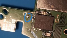
Hi, this pad here is an alternate point for 3.3v on OLED, right?
Is there any downside to using it instead of soldering to the capacitor, other than the wire being like 5mm longer?
I got kinda unlucky (and too stubborn) on the last OLED and ended up damaging the IC next to the capacitors. So I'd love to avoid them now
 

Attachments

  • IMG_20231211_054420_635.jpg
    IMG_20231211_054420_635.jpg
    139.5 KB · Views: 25

BlueBeans

Well-Known Member
Member
Joined
May 2, 2023
Messages
270
Trophies
0
Age
32
XP
270
Country
United States
Hi, this pad here is an alternate point for 3.3v on OLED, right?
Is there any downside to using it instead of soldering to the capacitor, other than the wire being like 5mm longer?
I got kinda unlucky (and too stubborn) on the last OLED and ended up damaging the IC next to the capacitors. So I'd love to avoid them now
I’ve never seen that used as the 3.3v but you can use either one of those caps for 3.3v I believe.
 

psycho-neon

Well-Known Member
Member
Joined
Nov 12, 2023
Messages
132
Trophies
0
XP
320
Country
Philippines
Hi, this pad here is an alternate point for 3.3v on OLED, right?
Is there any downside to using it instead of soldering to the capacitor, other than the wire being like 5mm longer?
I got kinda unlucky (and too stubborn) on the last OLED and ended up damaging the IC next to the capacitors. So I'd love to avoid them now
That looks like a ground point only. Double check with multimeter and make sure.
 

abal1000x

Well-Known Member
Member
Joined
Jun 5, 2022
Messages
1,062
Trophies
0
XP
1,369
Country
Gaza Strip
Hi, this pad here is an alternate point for 3.3v on OLED, right?
Is there any downside to using it instead of soldering to the capacitor, other than the wire being like 5mm longer?
I got kinda unlucky (and too stubborn) on the last OLED and ended up damaging the IC next to the capacitors. So I'd love to avoid them now
I've use that point, and its the best point for oled back pcb 3.3V.
https://gbatemp.net/threads/picofly-a-hwfly-switch-modchip.622701/post-10266604

Heres the whole 3.3V on oled back pcb.
a.png


Front Pcb
b.png
 
Last edited by abal1000x,

LuigiGad

Well-Known Member
Member
Joined
May 7, 2023
Messages
160
Trophies
0
Age
56
XP
471
Country
Italy
You heated that resistor too much it not function well anymore. I don't know which tip you was using. Using small tip for small resistor is recommended. Do it quickly and not linger on it too long.
no, I totally exclude it, I've made lots of OLEDs and I'm very light at soldering. To exclude.
 

Bradle6

Well-Known Member
Member
Joined
Jan 7, 2020
Messages
223
Trophies
0
Age
29
XP
552
Country
United Kingdom
Hi, this pad here is an alternate point for 3.3v on OLED, right?
Is there any downside to using it instead of soldering to the capacitor, other than the wire being like 5mm longer?
I got kinda unlucky (and too stubborn) on the last OLED and ended up damaging the IC next to the capacitors. So I'd love to avoid them now

What is that ic for. As maybe I did that because the switch works but no touchscreen on the oled and I can't find the problem
 

Vigintiduo

Well-Known Member
Newcomer
Joined
Sep 13, 2023
Messages
57
Trophies
0
Age
32
XP
165
Country
Italy
I've use that point, and its the best point for oled back pcb 3.3V.
https://gbatemp.net/threads/picofly-a-hwfly-switch-modchip.622701/post-10266604

Heres the whole 3.3V on oled back pcb.
View attachment 408258

Front Pcb
View attachment 408259

Thank you for all the insight as usual! I might just use that point even though I'm going for a front install. I'm still on the trauma from the previous unlucky experience lol. Hopefully the wire running just a bit longer won't be an issue

What is that ic for. As maybe I did that because the switch works but no touchscreen on the oled and I can't find the problem
It's a buck boost, so I doubt it. You should probably check somewhere else on the board. I'm kinda new to oleds so I don't know if the touch screen is still together with the cartridge reader
 

superxoi

Well-Known Member
Member
Joined
May 8, 2020
Messages
159
Trophies
0
Age
32
XP
832
Country
Vietnam
Another OLED done! Got the hang of using the dat0 adapter on how to properly anchor it without resorting to kamikaze method. ❤️View attachment 408268
i have just gotten a bad batch of dat0 adapter now. these chinese seller are tricky one. first i bought 15 they shipped me the good one this time i bought 50 and i got this shitty ones. i will rely on reballing waiting for another batch.
 

Attachments

  • NUM_0000_0016.JPG
    5.5 MB · Views: 20

Myst0gan

Well-Known Member
Member
Joined
Oct 17, 2023
Messages
122
Trophies
0
XP
124
Country
United States
Post your work. I have a v1 here I need to do and I’ll post my work as well. Are you using a flex cable or mosfets?
Post automatically merged:


I saw this one as well but there are no gerber files 😔
I gave up, it could be the r2040. I'll test them on the next console that I get. I've modded a switch lite last week, using the rp2040 from the same batch that I've ordered from Ali and it worked like a charm... So I was thought others are fine too

Im using the 3.3v from the nand. Never had issue with it, already modded 8nos of v1/v2 with that setup.

The only thing I take from the board was ground and the cpu, the rest on nand. Your case is different for sure. Maybe you bridge something else.
How do you do that?? I had hell of a time just to connect a wire from nand to the broken pad on the board
 
  • Sad
Reactions: BlueBeans

Vigintiduo

Well-Known Member
Newcomer
Joined
Sep 13, 2023
Messages
57
Trophies
0
Age
32
XP
165
Country
Italy
I finished installing picofly on my OLED, but I'm getting ** RST not connected, while it's definitely there. Also got black screen.
After desoldering the rp2040, I can safely boot into ofw, so there's no actual damage.
I went kamikaze and with the 3.3v point on the back.
I see that sometimes the RST error is caused by the 3.3v line, but I got the right one, albeit with longer wires. It only turns on when I press the power button.
Diode readings are fine on every line, however with the rp2040 installed, I can't even hear the soft "whirring" sound that comes from the console, meaning it's probably stuck in some really early boot phase.
What's the best way to troubleshoot this?
 

Site & Scene News

Popular threads in this forum

General chit-chat
Help Users
    K3Nv2 @ K3Nv2: Keep current Gen consoles stock mod last gen imo