Game Boy Micro Not charging, I think it's the Diode, looking for help

JohnnyPhantom

Member
OP
Newcomer
Joined
Aug 15, 2014
Messages
12
Trophies
0
Age
38
Location
Warwick, Rhode Island
XP
157
Country
United States
Hey Everyone,
I picked up a Game Boy Micro that was in rough shape. It was listed on FaceBook Marketplace as working, but will not charge. It also came with an official Game Boy Micro Link cable, so that was pretty cool. When I got the device, it you install an already charged battery into the unit, it would play just like normal. However, the system will not charge the battery, the seller thought it was a bad charge port and that it might be a great candidate for a USB-C mode. I figured it was a fuse issue, seemed like a common fault. I took the system apart and tested the fuses, both are good. I don't see any board damage, nothing stands out. I tested with a couple known good batteries and chargers and no improvement. For the heck of it, I did do the USB-C mod with HDR's adapter PCB. IT looks great. I can plug in a powered USB-C cable and get voltage, but still no dice on charging. I did some online research and not sure what's left. I did find a photo online that shows the approximate voltage on several positions of the mainboard. I get some of the readings shown, I hadn't measured anything from the chip on the right side of the photo yet.

OoXyOR5.png
image_123650291.JPG


I've highlighted in purple the voltages I get when measuring (or close to the voltage, as it varies based upon the batteries charge) the ones I haven't highlighted in purple are areas where I get 0V readings. To me, it looks like the voltage comes in from the charger, comes down to the D1 PS diode and then stops. I get the 4V on the right of the diode and 0V on the left side of it. I took my digital multimeter and set the dial to diode testing, and when I put the probes on the sides of the diode I get a reading of 000000 and if I switch the ends which probes are on, I still get a reading of 000000. From what I've seen on how to test diode YouTube videos, this is a sign of a shorted diode. So my current assumption is the diode is bad.

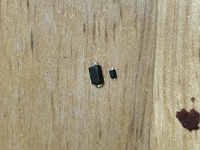
Only issue is, I have NO idea on what to order as a suitable diode replacement. Does any one know what diodes I can order to replace this bad one? On my main board it looks like the diode has the marking of "S3" on it, looking online I also see other variants that have ":2W" on the diode, but I'm unable to find anything about those online.

If I'm missing anything and I'm completely wrong, and this isn't signs of a failed diode, please let me know what else I can test, I really want to revive this system. I have 2 other Game Boy Micros (a normal black one with a silver faceplate, and a mint condition 20th anniversary/Famicom edition one) that are great shape and I don't like to use them as I want to preserve them, I was excited about this bad Game Boy Micro since it's in rough shape and I can just toss it in my pocket without a care and use it as my daily driver and with the bonus of a USB-C port, I don't have to worry about carrying around a proprietary charger for it, and USB-C charger will do.

Thanks in advance everyone! Hoping we can help save this system! B-)

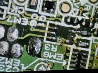
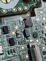
I've included photo's of the front and back of my PCB incase anyone can spot any potential issues.
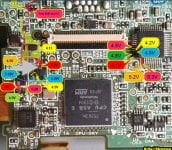
IMG_2784.jpg
IMG_2783.jpg
 

Ozito

Who you gonna call?
Member
Joined
Mar 20, 2006
Messages
411
Trophies
1
Location
Sweden
XP
840
Country
Sweden
You found my pics :)
Well done with the troubleshooting and detailed post👌

TLDR; Try the SSM5818SLGP it might solve your problem.

You're correct, It seems like the diode is dead with those results you get on the multimeter.
The "S3" code can be looked up if you search for "smd marking codes", you'll probably see this fantastic piece of resource in your results. "Ctrl f" your way to "S3" and in there you'll see a list of diodes.

Let's get some things clear first, before we start looking for a replacement.
We know from the first pic, that the B+ (yellow) circuit has about 4.x Volts when being charged and probably drops to 3.x Volts when powered by the battery. We can also find out from the specs printed on the charger that, the output is rated to 5.2 Volts and 320 milliamps.
Armed with these numbers we are now going to do some guessing.

My first guess is that the voltage on the B+ circuit doesn't go higher nor barely reaches 5.2V when battery is being charged.
My second guess is that the charge circuit dosen't go higher than 320mA and thus the diode doesn't see more action than that.
My third guess is that any diode that blocks voltages from 3V and up, and also has an "average forward current" of at least 320mA, should be fine for this circuit.

So now with that in mind, let's find a replacement diode.
The diode that should fit that circuit is the "SSM5818SLGP", why? Because next to it you can read "SBR, 30V, 500mA, Vf<0.43V(500mA)" That means it blocks 30V and safely conducts 500mA.
Do you want more specs? Have a look at the datasheet.

I'm a big dork for these GBMs, I too have the 20th happy mario edition, bought it new in 2011 for approx 100USD.
Now let's try and keep them away from the trash and fix all of them.
 
Last edited by Ozito,

JohnnyPhantom

Member
OP
Newcomer
Joined
Aug 15, 2014
Messages
12
Trophies
0
Age
38
Location
Warwick, Rhode Island
XP
157
Country
United States
You found my pics :)
Well done with the troubleshooting and detailed post👌

TLDR; Try the SSM5818SLGP it might solve your problem.

You're correct, It seems like the diode is dead with those results you get on the multimeter.
The "S3" code can be looked up if you search for "smd marking codes", you'll probably see this fantastic piece of resource in your results. "Ctrl f" your way to "S3" and in there you'll see a list of diodes.

Let's get some things clear first, before we start looking for a replacement.
We know from the first pic, that the B+ (yellow) circuit has about 4.x Volts when being charged and probably drops to 3.x Volts when powered by the battery. We can also find out from the specs printed on the charger that, the output is rated to 5.2 Volts and 320 milliamps.
Armed with these numbers we are now going to do some guessing.

My first guess is that the voltage on the B+ circuit doesn't go higher nor barely reaches 5.2V when battery is being charged.
My second guess is that the charge circuit dosen't go higher than 320mA and thus the diode doesn't see more action than that.
My third guess is that any diode that blocks voltages from 3V and up, and also has an "average forward current" of at least 320mA, should be fine for this circuit.

So now with that in mind, let's find a replacement diode.
The diode that should fit that circuit is the "SSM5818SLGP", why? Because next to it you can read "SBR, 30V, 500mA, Vf<0.43V(500mA)" That means it blocks 30V and safely conducts 500mA.
Do you want more specs? Have a look at the datasheet.

I'm a big dork for these GBMs, I too have the 20th happy mario edition, bought it new in 2011 for approx 100USD.
Now let's try and keep them away from the trash and fix all of them.
Thank you thank you thank you soo much for your reply! I had almost gave up hope I’d find what diode I would need to attempt this repair. I’d like to go ahead and order the diode to have and swap it out and see what happens, I’ll also test what you suggested and see what results I can come up with. Quick question, I tried my usual places but can’t seem to find SSM5818SLGP would you happen to know where I can order them?

Thank you again!
 
  • Like
Reactions: gangan

Ozito

Who you gonna call?
Member
Joined
Mar 20, 2006
Messages
411
Trophies
1
Location
Sweden
XP
840
Country
Sweden
Yes I had difficulties finding it too.

The "1N5817W 1N5818W 1N5819W" should also be fine, the names are not specific diodes from a manufacturer but a standard set by the "JEDEC" (have been learning some stuff too) that indicates type of component and characteristics as can be seen in any datasheet pertaining to those names.

1703153864502.png


One last thing, in 2021 I was able to map out where the sandwiched flex cable connects between the two boards.
Doing that allowed me to repair a GBM with no backlight I bought back in 2013 when I didn't knew how to, so don't give up, put things aside for a later repair and keep learning in the mean time!
 

JohnnyPhantom

Member
OP
Newcomer
Joined
Aug 15, 2014
Messages
12
Trophies
0
Age
38
Location
Warwick, Rhode Island
XP
157
Country
United States
Yes I had difficulties finding it too.

The "1N5817W 1N5818W 1N5819W" should also be fine, the names are not specific diodes from a manufacturer but a standard set by the "JEDEC" (have been learning some stuff too) that indicates type of component and characteristics as can be seen in any datasheet pertaining to those names.

View attachment 409791

One last thing, in 2021 I was able to map out where the sandwiched flex cable connects between the two boards.
Doing that allowed me to repair a GBM with no backlight I bought back in 2013 when I didn't knew how to, so don't give up, put things aside for a later repair and keep learning in the mean time!
I ordered the diode from Aliexpress, came in today, so I'm installing it now. It's much much smaller than the original, about 1/4th the size. I'll give it my best and report back

1N5819WT S4 SOD523 from https://www.aliexpress.us/item/2251...st_main.5.16761802y16igx&gatewayAdapt=glo2usa

Maybe I should have gotten the 1N5819WS or 1N5819?
Post automatically merged:

I decided to hold off, and ordered this https://www.digikey.com/en/products/detail/evvo-semi/1N5819W/21407174 since I was doing a DigiKey order for another project
 

Attachments

  • tempImageP9f8dv.png
    tempImageP9f8dv.png
    9 MB · Views: 18
Last edited by JohnnyPhantom,
  • Like
Reactions: Ozito

Ozito

Who you gonna call?
Member
Joined
Mar 20, 2006
Messages
411
Trophies
1
Location
Sweden
XP
840
Country
Sweden
That's tiny! 😅

Should've mentioned that the "SOD" number indicates the size of the package. SOD523 is smaller than SOD123. As can be seen in the table.

https://electrical-information.com/package-types-sod/

1704466613536.png
1704466629575.png

I decided to hold off, and ordered this https://www.digikey.com/en/products/detail/evvo-semi/1N5819W/21407174 since I was doing a DigiKey order for another project

It's a SOD123 witch means that it's minimum 3.5mm long from pin to pin as can be seen in the datasheet.

1704467625198.png

What you could do is measure the length of the broken diode to see if it is 3.5mm or smaller, that way you'll know if the "SOD123" is the correct (I think it is) size.

Keep us updated with the results and have a nice weekend.
 

gangan

Member
Newcomer
Joined
Mar 13, 2022
Messages
22
Trophies
0
Age
32
Location
usa
XP
76
Country
United States
This post is giving me a lot of hope. About to go test the GBM I got recently that has the exact described issue. Been scratching my head on what could be causing it for about a week. Fuses and such are fine. Going to go test the diode in a bit to see if that's what's going on with mine as well. Tried following traces, but can't figure out where some of them go. That voltage picture you found that Ozito made looks super helpful as well.
 
  • Like
Reactions: Ozito

Ozito

Who you gonna call?
Member
Joined
Mar 20, 2006
Messages
411
Trophies
1
Location
Sweden
XP
840
Country
Sweden
This post is giving me a lot of hope. About to go test the GBM I got recently that has the exact described issue. Been scratching my head on what could be causing it for about a week. Fuses and such are fine. Going to go test the diode in a bit to see if that's what's going on with mine as well. Tried following traces, but can't figure out where some of them go. That voltage picture you found that Ozito made looks super helpful as well.

So what's the prognosis on the diode? 🙂
 

gangan

Member
Newcomer
Joined
Mar 13, 2022
Messages
22
Trophies
0
Age
32
Location
usa
XP
76
Country
United States
So what's the prognosis on the diode? 🙂
The diode seems fine. All other voltages on the left of the board seem fine except for this particular leg on (what I assume) is this transistor. Figured that component may be bad so transferred the exact component from my working micro over (voltage was reading correctly on it), but still reads very low on the one that isn’t charging. I don’t recall exactly, but it was a little over 1 volt, I believe. So at a loss again. Lol
 

Attachments

  • IMG_0050.jpeg
    IMG_0050.jpeg
    1.5 MB · Views: 22

Ozito

Who you gonna call?
Member
Joined
Mar 20, 2006
Messages
411
Trophies
1
Location
Sweden
XP
840
Country
Sweden
Hmm.. so that 4.7V trace shows 1V when connected to the charger but you still get 4.5V and 5.18V on the other pins and 4.5 after the resistor? It shouldn't be possible, please do the measurements again and let's find out.
 

gangan

Member
Newcomer
Joined
Mar 13, 2022
Messages
22
Trophies
0
Age
32
Location
usa
XP
76
Country
United States
Hmm.. so that 4.7V trace shows 1V when connected to the charger but you still get 4.5V and 5.18V on the other pins and 4.5 after the resistor? It shouldn't be possible, please do the measurements again and let's find out.
It's actually lower. I'm not sure of the best way to check these voltages. They read different depending on whether the battery is connected or not. With the battery connected, the top leg I pointed to previously shows .02v, so essentially nothing. The 1R2 (resistor?) reads 0.2v on each side. The diode reads 3.99v (which is the current battery voltage), but the test point after that, which should be reading 4.5v is 0.02 as well. So maybe it is the diode?

To be honest, I'm not entirely sure which way everything "flows" in this scenario. I'd planned to remove the diode from the board and test, or swap with my other board that is currently working to test, But the display connectors are right next to it, so can't use hot air. I'll need to wait for my smaller tips to come in the mail to make sure I don't melt those connectors.

Completely unrelated, but I also messed up my "good" board when plugging in the power adapter last night. It apparently had a decent amount of corrosion on the EM6 pad right next to where the power connector slot goes. I tested continuity on the other board and it seems like each link goes straight across. I've heard of other's just bridging each of those connections on other gameboys to bypass, any thoughts on that as well? As you can see, the corrosion essentially ate all the pads. I'll need to grind off some to reveal traces to get it connected either way.

I still have the component, but the lid is torn off and full of corrosion on each of the contacts. I might be able to grind some away, but I'm not 100% sure that this component is absolutely necessary.
 

Attachments

  • IMG_3839.JPG
    IMG_3839.JPG
    5.8 MB · Views: 23

Ozito

Who you gonna call?
Member
Joined
Mar 20, 2006
Messages
411
Trophies
1
Location
Sweden
XP
840
Country
Sweden
To prevent thread hijacking, start a new thread with your errors and what you've done. In the meantime I'll disassemble a GBM and do some probing to see where those vias between the diode and transistor (seen in purple) end up and what components are connected there, since it seems like something is shortcut thus preventing the proper voltages to be present.

1704712494065.png


Also, I don't think your diode is broken. I say that because if it were bad then you wouldn't have 2 different voltages on the pins.
The diode is working like a "one-way valve" which allows current to flow in one direction. In this case it blocks the yellow arrows coming from the battery circuit. The symbol in purple represents the diode and shows the "blocking action" and direction of the current.

1704714335648.png


And regarding the mess up with your good board, it looks repairable in my eyes but you'll need a fine tip soldering iron, thin enamel wire, flux and a steady hand.
 
Last edited by Ozito,

gangan

Member
Newcomer
Joined
Mar 13, 2022
Messages
22
Trophies
0
Age
32
Location
usa
XP
76
Country
United States
To prevent thread hijacking, start a new thread with your errors and what you've done. In the meantime I'll disassemble a GBM and do some probing to see where those vias between the diode and transistor (seen in purple) end up and what components are connected there, since it seems like something is shortcut thus preventing the proper voltages to be present.

View attachment 412669

Also, I don't think your diode is broken. I say that because if it were bad then you wouldn't have 2 different voltages on the pins.
The diode is working like a "one-way valve" which allows current to flow in one direction. In this case it blocks the yellow arrows coming from the battery circuit. The symbol in purple represents the diode and shows the "blocking action" and direction of the current.

View attachment 412671

And regarding the mess up with your good board, it looks repairable in my eyes but you'll need a fine tip soldering iron, thin enamel wire, flux and a steady hand.
Good idea. I created a new thread here: https://gbatemp.net/threads/gameboy-micro-powers-on-but-will-not-charge.645981/

I initially just posted here, as I figured my issue might be the same, but it is not. I tried to find where those vias went, but the opposite side is where the cartridge slot is, so I may be removing that with low melt solder in the near future to get a visual on it possibly :mellow:
 

gangan

Member
Newcomer
Joined
Mar 13, 2022
Messages
22
Trophies
0
Age
32
Location
usa
XP
76
Country
United States
Got the replacement diode in today, installed it. But no change in anything

Not sure what to check next
If we can’t get it figured out, or if it winds up being related to the charge IC or some other custom component, I’m wondering if we could fit something like this in. Possibly removing the usb c port from the board and locating it elsewhere (running wires from the port to wherever the actual board may fit) if there’s not room near the charging port.

As long as it’d all fit inside somewhere, I don’t see why it wouldn’t work. Just tap the b+ and b- on the board to the battery terminals.

https://www.ebay.com/itm/1158571723...C1flgHWS0C&var=&widget_ver=artemis&media=COPY
 
  • Like
Reactions: Ozito

Ozito

Who you gonna call?
Member
Joined
Mar 20, 2006
Messages
411
Trophies
1
Location
Sweden
XP
840
Country
Sweden
It seems like both of you have the same problem after all, which is the missing voltages pre and post the 1ohm resistor.

Check if those voltages are present on the power management IC when battery and charger is connected.
For now, those two legs seem to be the only place where the vias are connected to.

slice1.png
 

gangan

Member
Newcomer
Joined
Mar 13, 2022
Messages
22
Trophies
0
Age
32
Location
usa
XP
76
Country
United States
Thank you for the update. I had actually tested mine late last night and forgot to post. The voltages there were reading very low as well. I’m assuming the chip is damaged. Tried searching online and assume it’s a custom chip or unavailable.

I ordered those small usb c charging boards so hopefully I’ll be able to fit one of those somewhere in the housing. Assume I may need to remove the usb c connector from that board and run enamel wire as I doubt they’re small enough to fit where the original charge port should go.
 

Site & Scene News

Popular threads in this forum

General chit-chat
Help Users
  • No one is chatting at the moment.
    K3Nv2 @ K3Nv2: Lol rappers still promoting crypto