Hacking Hardware Picofly - a HWFLY switch modchip

lightninjay

Well-Known Member
Member
Joined
Mar 28, 2023
Messages
560
Trophies
0
Age
31
XP
1,375
Country
United States
Seriously... I get an error "

Seriously... I get an error "failed to load PDF document"
Post automatically merged:


Seriously... I get an error "failed to load PDF document"
Yikes...

You're supposed to delete the ".pdf" at the end of the file.

Please read the definitive guide.
 

Elpoep

Member
Newcomer
Joined
Jun 27, 2023
Messages
19
Trophies
0
Age
33
XP
24
Country
United States
Yikes...

You're supposed to delete the ".pdf" at the end of the file.

Please read the definitive guide.
Thanks for the help!
Post automatically merged:

Yikes...

You're supposed to delete the ".pdf" at the end of the file.

Please read the definitive guide.
I think I flashed to picofly correctly. To do a quick check to see if anything popped up on my PC screen after my flashing attempt I replugged the picofly into my PC. After replugging the picofly into the PC, The blue light came on and then it began blinking yellow -- it blinked yellow six times and then stopped. Does this indicate that the chip has been programmed correctly?
 
Last edited by Elpoep,

lightninjay

Well-Known Member
Member
Joined
Mar 28, 2023
Messages
560
Trophies
0
Age
31
XP
1,375
Country
United States
Thanks for the help!
Post automatically merged:


I think I flashed to picofly correctly. To do a quick check to see if anything popped up on my PC screen after my flashing attempt I replugged the picofly into my PC. After replugging the picofly into the PC, The blue light came on and then it began blinking yellow -- it blinked yellow six times and then stopped. Does this indicate that the chip has been programmed correctly?
Yes
 

POPOLO

Active Member
Newcomer
Joined
Apr 17, 2023
Messages
34
Trophies
0
Age
44
XP
194
Country
Japan
Thanks for the help!
Post automatically merged:


I think I flashed to picofly correctly. To do a quick check to see if anything popped up on my PC screen after my flashing attempt I replugged the picofly into my PC. After replugging the picofly into the PC, The blue light came on and then it began blinking yellow -- it blinked yellow six times and then stopped. Does this indicate that the chip has been programmed correctly?
YES
 

Attachments

  • 01.mp4
    1.1 MB
  • Like
Reactions: Elpoep

Elpoep

Member
Newcomer
Joined
Jun 27, 2023
Messages
19
Trophies
0
Age
33
XP
24
Country
United States
So I read the guide but I'm not using method w/ mosfet; i'm using the flex cable. because the cpu is the same and I'm not using HWLFLY can I just use a V2 ribbon?
The Version 3 ribbon just seems to arc over to reach the HWLFY, I'm obviously team RP2040, and I'm just going to solder to the pins on the flex cable anyway.

And lastly, don't you need to cure the UV-cure solder mask with a UV light?
 
Last edited by Elpoep,

lightninjay

Well-Known Member
Member
Joined
Mar 28, 2023
Messages
560
Trophies
0
Age
31
XP
1,375
Country
United States
So I read the guide but I'm not using method w/ mosfet; i'm using the flex cable. because the cpu is the same and I'm not using HWLFLY can I just use a V2 ribbon?
The Version 3 ribbon just seems to arc over to reach the HWLFY, I'm obviously team RP2040, and I'm just going to solder to the pins on the flex cable anyway.

And lastly, don't you need to cure the UV-cure solder mask with a UV light?
Screenshot_20230627-164031_PDF Reader - Hi Read.png

I cannot teach reading comprehension, what else would "UV-cure" mean?
 
  • Like
Reactions: impeeza and Switxh

Dee87

Well-Known Member
Member
Joined
Mar 19, 2023
Messages
1,139
Trophies
1
XP
1,578
Country
Germany
Hi, I have the same error code ( " *=* No eMMC block 0 read (eMMC init failure?)" ) with several OLEDs! I thought it was my wiring, the picofly (2.74) and the mosft cable that was messed up. I soldered a HWFly v5 core the console starts without problem?

I have to tell you, I only boot on the original fw with the pico installed
Try 2.73
Edit:Well forget just saw u tried it Xd
 

bilalhassan341

Well-Known Member
Member
Joined
Apr 1, 2023
Messages
138
Trophies
0
XP
271
Country
United States
I flashed in 2.73 I did the wiring 3 times and still the same problem.


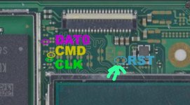
Are there any resistors on the Dat0/clk/cmd?. On video I can't tell if there is any.
Post automatically merged:

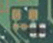
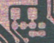
The two points below the Rst circled. Is these points are also RST points?

Edit: They are connected

Confirmed by using http://balika011.hu/switch/lite/.
 

Attachments

  • IMG-20230628-WA0005.jpg
    IMG-20230628-WA0005.jpg
    71.8 KB · Views: 47
  • Screenshot 2023-06-28 at 2.14.16 AM.png
    Screenshot 2023-06-28 at 2.14.16 AM.png
    360.7 KB · Views: 37
  • Screenshot 2023-06-28 at 2.14.08 AM.png
    Screenshot 2023-06-28 at 2.14.08 AM.png
    399.3 KB · Views: 39
Last edited by bilalhassan341,
  • Like
Reactions: chronoss and QuiTim

JaRocker

Well-Known Member
Member
Joined
May 3, 2018
Messages
341
Trophies
0
XP
1,486
Country
Jamaica
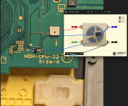
finally did one of these RP2040 installs; good learning experience after several years since my last SAMD21 install. went with a seeed xiao RP2040, dual mosfet. relocated the status LED to the front of the board where the (nearly) unused home button LED was, so it can act as an external status indicator. boot times seem good. quite pleased

View attachment 379924 View attachment 379925

View attachment 379927
hey how would you go about doing this with that rgb led on the RP2040 zero/tiny
 

Attachments

  • led.png
    led.png
    2.1 MB · Views: 49
Last edited by JaRocker,

StormySky16

Member
Newcomer
Joined
May 22, 2022
Messages
5
Trophies
0
Age
22
Location
USA
XP
65
Country
United States
I've seen that it's possible to install a HWFLY core modchip into the OLED, I was wondering if anyone here knows if this is possible with the RP2040 Core? I imagine it is, but I'm not sure how to go about figuring out where the manual soldering points are on the chip.
 

Dee87

Well-Known Member
Member
Joined
Mar 19, 2023
Messages
1,139
Trophies
1
XP
1,578
Country
Germany
I've seen that it's possible to install a HWFLY core modchip into the OLED, I was wondering if anyone here knows if this is possible with the RP2040 Core? I imagine it is, but I'm not sure how to go about figuring out where the manual soldering points are on the chip.
Sure it is but I would suggest looking in other threads cause this isn't about hwfly chips ;-) .
Rather try a thread dedicated to the hwfly rp2040 or google or ask ur chip supplier.

The supported chips are pinned in the important post or in the Picofl Aio thread on page one
 

vulp_vibes

Well-Known Member
Member
Joined
Mar 13, 2013
Messages
104
Trophies
1
XP
1,563
Country
United States
hey how would you go about doing this with that rgb led on the RP2040 zero/tiny

that pinout should be correct; they appear to be using the same LED. also, I will likely be doing another install soon as I repaired a second lite board yesterday, so I will see if I can figure out a method that leaves the original home button LED intact.
 
  • Like
Reactions: Takezo-San

morganno

Active Member
Newcomer
Joined
Aug 7, 2018
Messages
27
Trophies
0
Age
48
XP
304
Country
France
Are there any resistors on the Dat0/clk/cmd?. On video I can't tell if there is any.
Post automatically merged:

The two points below the Rst circled. Is these points are also RST points?

Edit: They are connected

Confirmed by using http://balika011.hu/switch/lite/.


thanks friend, just wanted to fix the switc version, it's an OLED not a lite.

to answer your question I have the resistors, 47ohm on the D0, clk and on the cmd.

on the rp2040 zero they are behind the rp2040 zero solder on the pcb.

on rp2040 timy I replaced the resistors.

after I did a test with the same wiring with HWFly does it work? For me it's not a wiring problem!

 
  • Like
Reactions: bilalhassan341

lightninjay

Well-Known Member
Member
Joined
Mar 28, 2023
Messages
560
Trophies
0
Age
31
XP
1,375
Country
United States
Last edited by lightninjay,

JaRocker

Well-Known Member
Member
Joined
May 3, 2018
Messages
341
Trophies
0
XP
1,486
Country
Jamaica
that pinout should be correct; they appear to be using the same LED. also, I will likely be doing another install soon as I repaired a second lite board yesterday, so I will see if I can figure out a method that leaves the original home button LED intact.
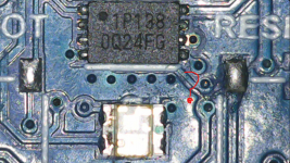
this is the RGB led that is on the zero/tiny I'm unable to find the pinout for it
 

Attachments

  • rgb led zero tiny.png
    rgb led zero tiny.png
    1.4 MB · Views: 44

Elpoep

Member
Newcomer
Joined
Jun 27, 2023
Messages
19
Trophies
0
Age
33
XP
24
Country
United States
any suggestions for removal of the buttons and usbc port using hot air -- i'm using Celcius temp? I had a horrible time trying to get the buttons and usbc port off the 2040 zero -- for the buttons they finally came off at 280 and the usbc at 300 -- I think I fubar - ed the board though! I bought two just in case the first one had issues. I did pre flux and tent the connecting points. Any temp suggestions?
Any advice on testing the board before I try and wire?
 

Site & Scene News

Popular threads in this forum

General chit-chat
Help Users
    K3Nv2 @ K3Nv2: https://youtu.be/sGvT5FKSiyk?si=TYqsdjjbF-4N8Xc8