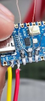
are you using UV Resin to hold the mosfets down?View attachment 369482
Here is a composite image I just took of a double mosfet install I am doing on a switch lite. The circles are the general points of interest and where they need to be hooked up. I jumpered between the gate pins on the mosfets and ran a single wire to the rp2040 to keep wire clutter down, as has been suggested previously.
You are using an out of date browser. It may not display this or other websites correctly.
You should upgrade or use an alternative browser.
You should upgrade or use an alternative browser.
Staff Posts
Recent threadmarks
sharing files
Important Posts
Recent threadmarks
FirmwaresYes, I use a toothpick and place a small dot of resin (smaller than the mosfet) just above/below where I want to place the mosfet, then gently place the mosfet on the edge of the droplet of resin so that it wicks to the side of the mosfet. Once it has wicked into place, I cure it with a UV laser pointer I have for quick hardening.are you using UV Resin to hold the mosfets down?
Kudos on the work with that Gate wire. Very impressive.View attachment 369482
Here is a composite image I just took of a double mosfet install I am doing on a switch lite. The circles are the general points of interest and where they need to be hooked up. I jumpered between the gate pins on the mosfets and ran a single wire to the rp2040 to keep wire clutter down, as has been suggested previously.
I actually have some of that cost a bit.I would suggest you get some lead solder 63/37 or similar. It makes everything easier. the one that you are using has a melting temp of 227° compared to Sn63/Pb37 of 183° or Sn62/Pb36/Ag2 of 179°
if you are in US you should have no problem getting Lead based solder (Kester is awesome).
Trying to get this stuff in EU is a nightmare.
Post automatically merged:
i dont know what issues you are facing but those cards are not good for anything.
Get a SanDisk, Samsung Evo or Kingstone Canvas.
Basically any established brand name (beware of fakes)
Have just removed all redundant on picofly, soldered the resistors and just about to do the mosfets.
For the people who say don't attempt this, attempt it - gotta learn some how.
Take your time though
Last edited by 789-Benny,
Learn on an OGXB or 360, much cheaper and perfect learning curve.I actually have some of that cost a bit.
Have just removed all redundant on picofly, soldered the resistors and just about to do the mosfets.
For the people who say don't attempt this, attempt it - gotta learn some how.
Take your time though
Says the guy who admitted to having several dead switch lite boards to practice on...I actually have some of that cost a bit.
Have just removed all redundant on picofly, soldered the resistors and just about to do the mosfets.
For the people who say don't attempt this, attempt it - gotta learn some how.
Take your time though

Why you so obsessed. Show me where this was said as well.Says the guy who admitted to having several dead switch lite boards to practice on...
Last edited by 789-Benny,
Why you so obsessed
789-Benny said:Both threads need archived and a new thread needs created, people have gone way off subject and talk mad shit

woof, use more fluxIs this good enough?
Yeah I'm actually using but it just melts away or when the solder melts the wires moveswoof, use more flux

What I mean is, if the flux is evaporating and you are having to leave your iron in place long enough that it all evaporates, you are doing something wrong.Yeah I'm actually using but it just melts away or when the solder melts the wires moves
You need to put a little flux ( enough to cover the pad ) an have your wire pre-tinned, then put a small glob of solder on your soldering iron tip, place the head of your wire/resistor in place near the pad, then bring the solder ball into contact with the flux and allow the solder to flow and shine.
The whole process happens in mere moments, you shouldn't be holding your iron in place for multiple seconds, with exception to soldering to the ground plane.
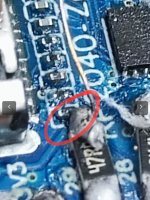
check for short/bridge here (might be just the angle of the photo)Yeah I'm actually using but it just melts away or when the solder melts the wires moves
Attachments
That actually make sense... I'm. Too tired to do it again now, I'll leave it for tomorrow, thank you.What I mean is, if the flux is evaporating and you are having to leave your iron in place long enough that it all evaporates, you are doing something wrong.
You need to put a little flux ( enough to cover the pad ) an have your wire pre-tinned, then put a small glob of solder on your soldering iron tip, place the head of your wire/resistor in place near the pad, then bring the solder ball into contact with the flux and allow the solder to flow and shine.
The whole process happens in mere moments, you shouldn't be holding your iron in place for multiple seconds, with exception to soldering to the ground plane.
Post automatically merged:
Yeah at first i thought it's making a contact with that resistor but i checked and it's fine actually.check for short/bridge here (might be just the angle of the photo)
good job broThe wait finally came to an end. I installed the first one last night but it did take me longer then I expected (thanks to 3v3 point)
On my search to find some 47R resistors locally, I stumbled upon IRF8714 (SO-8) Mosfet and I thought why not, lets give it a shot (the alternative was to use V1 flex on Mariko since I’m still waiting on the order from Ali with mosfets, resistors, wires and everything)
I only used one IRF8714 (connected to both caps) and everything works ok (Inspired by @dave22 layout, thank you)
Being an SO-8, the mosfet is a bit large so I cut the shield between the APU and memory just to be sure, but the upside is that it’s really easy to solder (because of the size and terminal layout)
I also cut the outer shield just for the fun of it and I think it looks nice this way.
The only issue that I had was the original 3v3 point on the cap. I guess after couple of tries I lost my cool a ripped the upper pad of cap (as it can be seen in the photo), and then I went for the alternative point in emmc which I soldered in 5sec.
Used 2.65 firmware and there was no problem whatsoever, everything works as intended.
I would like to thank @rehius for the amazing work and all the time he put in this project, and also @lightninjay for compiling the information on the pdf, @Adran_Marit for AIO and all the tips.
I think the real win here was finding this community of amazing people who share a passion of doing incredible things and their willingness to help others and bring them along in this journey.
CheersView attachment 366254View attachment 366256View attachment 366257View attachment 366258View attachment 366259View attachment 366260View attachment 366261
Flux to make it prettyIs this good enough?
P:S:- that's a piece of cleaning cotton there's no shorts on the 2nd smd res.
- Joined
- Jan 11, 2015
- Messages
- 754
- Trophies
- 0
- Age
- 36
- Location
- Makati
- Website
- leerz25.sitesled.com
- XP
- 2,185
- Country

emmc in slow mode. run emmc benchmark, redo your work, wires too longHi
Raspberry pi pico
Two sd same problem
Please help me
Bad 3V. point use the point above insteadAlready make over 50 Picofly 20 oled do have any problems before. Always make RGB mode is must be PURPLE not Pink
Similar threads
- Replies
- 3
- Views
- 1K
- Replies
- 2
- Views
- 304
- Replies
- 42
- Views
- 6K
Site & Scene News
New Hot Discussed
-
-
23K views
Wii U and 3DS online services shutting down today, but Pretendo is here to save the day
Today, April 8th, 2024, at 4PM PT, marks the day in which Nintendo permanently ends support for both the 3DS and the Wii U online services, which include co-op play...by ShadowOne333 179 -
16K views
Nintendo Switch firmware update 18.0.1 has been released
A new Nintendo Switch firmware update is here. System software version 18.0.1 has been released. This update offers the typical stability features as all other... -
16K views
The first retro emulator hits Apple's App Store, but you should probably avoid it
With Apple having recently updated their guidelines for the App Store, iOS users have been left to speculate on specific wording and whether retro emulators as we... -
15K views
Delta emulator now available on the App Store for iOS
The time has finally come, and after many, many years (if not decades) of Apple users having to side load emulator apps into their iOS devices through unofficial...by ShadowOne333 96 -
14K views
MisterFPGA has been updated to include an official release for its Nintendo 64 core
The highly popular and accurate FPGA hardware, MisterFGPA, has received today a brand new update with a long-awaited feature, or rather, a new core for hardcore...by ShadowOne333 54 -
10K views
Nintendo takes down Gmod content from Steam's Workshop
Nintendo might just as well be a law firm more than a videogame company at this point in time, since they have yet again issued their now almost trademarked usual...by ShadowOne333 113 -
9K views
A prototype of the original "The Legend of Zelda" for NES has been found and preserved
Another video game prototype has been found and preserved, and this time, it's none other than the game that spawned an entire franchise beloved by many, the very...by ShadowOne333 31 -
8K views
Nintendo "Indie World" stream announced for April 17th, 2024
Nintendo has recently announced through their social media accounts that a new Indie World stream will be airing tomorrow, scheduled for April 17th, 2024 at 7 a.m. PT...by ShadowOne333 53 -
8K views
Anbernic reveals specs details of pocket-sized RG28XX retro handheld
Anbernic is back with yet another retro handheld device. The upcoming RG28XX is another console sporting the quad-core H700 chip of the company's recent RG35XX 2024... -
8K views
"Famidash", a new fanmade demake for the NES of Geometry Dash
Homebrew games for retro consoles have seen a rise over the years thanks to new tools and community-made development kits, which help a lot in the process of creating...by ShadowOne333 23
-
-
-
179 replies
Wii U and 3DS online services shutting down today, but Pretendo is here to save the day
Today, April 8th, 2024, at 4PM PT, marks the day in which Nintendo permanently ends support for both the 3DS and the Wii U online services, which include co-op play...by ShadowOne333 -
113 replies
Nintendo takes down Gmod content from Steam's Workshop
Nintendo might just as well be a law firm more than a videogame company at this point in time, since they have yet again issued their now almost trademarked usual...by ShadowOne333 -
97 replies
The first retro emulator hits Apple's App Store, but you should probably avoid it
With Apple having recently updated their guidelines for the App Store, iOS users have been left to speculate on specific wording and whether retro emulators as we...by Scarlet -
96 replies
Delta emulator now available on the App Store for iOS
The time has finally come, and after many, many years (if not decades) of Apple users having to side load emulator apps into their iOS devices through unofficial...by ShadowOne333 -
77 replies
Nintendo Switch firmware update 18.0.1 has been released
A new Nintendo Switch firmware update is here. System software version 18.0.1 has been released. This update offers the typical stability features as all other...by Chary -
58 replies
TheFloW releases new PPPwn kernel exploit for PS4, works on firmware 11.00
TheFlow has done it again--a new kernel exploit has been released for PlayStation 4 consoles. This latest exploit is called PPPwn, and works on PlayStation 4 systems...by Chary -
55 replies
Nintendo Switch Online adds two more Nintendo 64 titles to its classic library
Two classic titles join the Nintendo Switch Online Expansion Pack game lineup. Available starting April 24th will be the motorcycle racing game Extreme G and another...by Chary -
54 replies
MisterFPGA has been updated to include an official release for its Nintendo 64 core
The highly popular and accurate FPGA hardware, MisterFGPA, has received today a brand new update with a long-awaited feature, or rather, a new core for hardcore...by ShadowOne333 -
53 replies
Nintendo "Indie World" stream announced for April 17th, 2024
Nintendo has recently announced through their social media accounts that a new Indie World stream will be airing tomorrow, scheduled for April 17th, 2024 at 7 a.m. PT...by ShadowOne333 -
52 replies
The FCC has voted to restore net neutrality, reversing ruling from 2017
In 2017, the United States Federal Communications Commission (FCC) repealed net neutrality. At the time, it was a major controversy between internet service providers...by Chary
-


