Hacking Hardware Picofly - a HWFLY switch modchip

jkyoho

Well-Known Member
Member
Joined
Sep 2, 2020
Messages
1,289
Trophies
0
Age
39
Location
TORONTO
Website
form.jotform.com
XP
2,225
Country
Canada
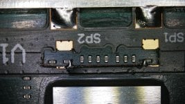
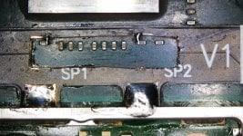
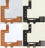
Hello, yesterday I asked about whether it was possible to use a v2 Flex in a v1, I saw this image on the internet of what I want to do but opposite, a v1 Flex in a V2 and I wanted to ask, how do you think I should do the installation ? the top side of the v1 smd on the right side of the Flex V2 and the bottom side of the v1 smd on the left side of the Flex v2? Or would I have to do it the other way around?
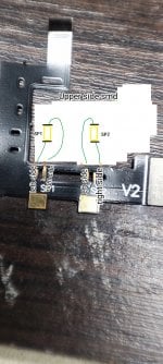
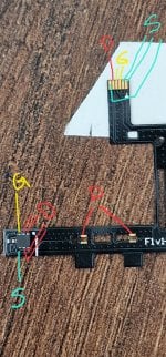
pay attention to the mosfet Drain, Source and Gate connectivity you should tell this is the way when v2 flex fits to v1 CPU
 

Attachments

  • IMG_20230425_120721.jpg
    IMG_20230425_120721.jpg
    1 MB · Views: 79
  • V1flexOnV2.jpg
    V1flexOnV2.jpg
    933.8 KB · Views: 92

QuiTim

Well-Known Member
Member
Joined
Mar 30, 2023
Messages
756
Trophies
0
XP
1,167
Country
Albania
Where did you find this? I need to to this (V1 flex on a V2) but I’m not sure the diagram is right.
V1 on v2 is easier. This is all the info you need.
You only need to solder the G(ate) from the top of the flex cable (2 middle pins)
Dont forget to solder the anchor because those are the S(ource) point.
Good luck
 

Attachments

  • 2020_0304_082337_033.JPG.jpg
    2020_0304_082337_033.JPG.jpg
    444.7 KB · Views: 80
  • GAFBlUIU8MU.jpg
    GAFBlUIU8MU.jpg
    582.9 KB · Views: 76
  • 20230419_172058.jpg
    20230419_172058.jpg
    1.7 MB · Views: 90

SorataVP69

Active Member
Newcomer
Joined
Mar 21, 2023
Messages
36
Trophies
0
Age
25
XP
82
Country
United States
Where did you find this? I need to to this (V1 flex on a V2) but I’m not sure the diagram is right.
https://gbatemp.net/threads/sxcore-installation-using-v1-flex-connector-on-v2-switch.611717/
Post automatically merged:

pay attention to the mosfet Drain, Source and Gate connectivity you should tell this is the way when v2 flex fits to v1 CPU
Hello, thank you very much for helping me, have you made that connection before?
 

aramirez0425

Member
Newcomer
Joined
Mar 31, 2023
Messages
11
Trophies
0
Age
36
XP
73
Country
United States
Has anyone had an issue with the modchip just blinking blue for about a minute and a half and then red. Console was glitching fine, for two weeks. Will a reset of the chip work ?
 

wikisa

Member
Newcomer
Joined
Feb 8, 2023
Messages
22
Trophies
0
Age
27
XP
124
Country
Poland
guys why some of you wires transistor to two resistors? and someone to only one
btw can someone send a good quality photo of v2 motherboard solder points?
I'm honestly have no idea also. I asked the same question and I've got following response:
Some people have had problems with only using one and got it working when using two. I'm not certain if the number of mosfets has been the actual issue though - I think it's more likely that the first one just wasn't working properly. Anyway, you can always test with one and add another if the rp2040 gives you cyan light.
When I checked it with multimeter there is no resistance (except multimeter probes ofc) between these points so I believe that's no reason to do so (if there is however I would like to know :) ).

Here's my photo of my mosfet installment which is using only one side of capacitor:

1682459992871.png


Everything ofc works.

I think just connecting any of black dots to mosfet's source and any of red dots to mosfet's drain is sufficient:

1682460585856.png
 
Last edited by wikisa,

QuiTim

Well-Known Member
Member
Joined
Mar 30, 2023
Messages
756
Trophies
0
XP
1,167
Country
Albania
Hello, yesterday I asked about whether it was possible to use a v2 Flex in a v1, I saw this image on the internet of what I want to do but opposite, a v1 Flex in a V2 and I wanted to ask, how do you think I should do the installation ? the top side of the v1 smd on the right side of the Flex V2 and the bottom side of the v1 smd on the left side of the Flex v2? Or would I have to do it the other way around?
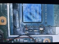
You could try cutting like this.
It would minimise the risk of shorting something and it would fit better.
But please check the pictures carefully and do more research.
 

Attachments

  • 20230426_000113.jpg
    20230426_000113.jpg
    1.4 MB · Views: 92
  • 1676818689087.jpeg.jpg
    1676818689087.jpeg.jpg
    1.4 MB · Views: 91
  • 366005876496863066.jpg
    366005876496863066.jpg
    44.4 KB · Views: 84
  • Like
Reactions: jkyoho

jkyoho

Well-Known Member
Member
Joined
Sep 2, 2020
Messages
1,289
Trophies
0
Age
39
Location
TORONTO
Website
form.jotform.com
XP
2,225
Country
Canada
  • Like
Reactions: QuiTim

R-Couto

Member
Newcomer
Joined
Mar 30, 2023
Messages
11
Trophies
0
Age
28
XP
57
Country
Brazil
Good night everyone, my RP Chip arrived Today and I saw that the unlock_uf2 file no longer has it, I would like to know if I still need it or I just need to put the FW 2.6x file for picofly to work, another doubt can I use flex V2 in a lite and solder the two Flex points to the chip?
 

jkyoho

Well-Known Member
Member
Joined
Sep 2, 2020
Messages
1,289
Trophies
0
Age
39
Location
TORONTO
Website
form.jotform.com
XP
2,225
Country
Canada
Good night everyone, my RP Chip arrived Today and I saw that the unlock_uf2 file no longer has it, I would like to know if I still need it or I just need to put the FW 2.6x file for picofly to work, another doubt can I use flex V2 in a lite and solder the two Flex points to the chip?
you don't need unlock.uf2 if you flash any fw 2.6+ on your rp2040
 
  • Like
Reactions: R-Couto

FreeLander

Well-Known Member
Member
Joined
Apr 6, 2023
Messages
350
Trophies
0
Age
35
XP
467
Country
United States
When I checked it with multimeter there is no resistance (except multimeter probes ofc) between these points so I believe that's no reason to do so (if there is however I would like to know :) ).

This has cost me an afternoon working on MOSFET. I installed it pretty well, using one and then two, but I wouldn't get a diode reading and logically I thought it didn't work. Dedee suggested I tried it out and turned out it worked perfectly. I guess there's no diode reading when using MOSFETs directly?
Post automatically merged:

I was doing my Switch installation with a 0.3mm enameled wire, and I broke too many traces. I couldn't find 0.2mm anywhere near me. Luckily, BNTECHGO listed a one-lb 32 AWG in my local shop, Oh boy did it not make all the difference. Looks red and sexy too.

0.2mm wire is the way to go like many have here said.
71X4ohNSoeL._AC_SL1500_.jpg
 
Last edited by FreeLander,

carlozgd

New Member
Newbie
Joined
Apr 26, 2023
Messages
1
Trophies
0
Age
30
XP
29
Country
Colombia
hi guys
while trying to use the CMD alternative point I damaged that resistance, could someone be so kind as to tell me what its value is
sorry for my english from google xD
 

Attachments

  • 222.png
    222.png
    1.3 MB · Views: 95

FreeLander

Well-Known Member
Member
Joined
Apr 6, 2023
Messages
350
Trophies
0
Age
35
XP
467
Country
United States
Reporting my RP pico successfully glitching after being cut as per @rehius and @Dee87's diagram.

Looks nice for a proof-of-concept. I came to notice that the Dat0 point on RP Pico is very fragile so I engraved a trace right next to the RP's chip, this made me keep the other side of pins that would have been otherwise cut, but I needed the ground on that side to not make it messy next to all the resistors, not to say it doesn't look messy anyways lol.
IMG_6798.JPG

Thank you @rehius and @Dee87. You guys have been very helpful and responsive.
 
  • Love
Reactions: Dee87

Site & Scene News

Popular threads in this forum

General chit-chat
Help Users
  • SylverReZ @ SylverReZ:
    Worst would be getting a DRM rootkit from using audio CDs and then Sony getting sued.
  • K3Nv2 @ K3Nv2:
    Least I can throw the nvme at neighbors now
  • DinohScene @ DinohScene:
    get a 2 TB NVMe from amazon, return the fucked one, get replacement and send that one to me
  • K3Nv2 @ K3Nv2:
    Easier way buy one with a preadded heatsync pop the heat sync open
  • K3Nv2 @ K3Nv2:
    Some nerd at Amazon warehouse may tell the end of the colors off
  • DinohScene @ DinohScene:
    I'd like a 990 pro tyvm <З
  • K3Nv2 @ K3Nv2:
    Gen 5s going to be crazy expensive at like 10k transfer
  • K3Nv2 @ K3Nv2:
    $300for 2tb
  • DinohScene @ DinohScene:
    don't have anything that can take PCIe5
  • K3Nv2 @ K3Nv2:
    It's still m.2 form just the next gen
  • DinohScene @ DinohScene:
    ew crucial
  • K3Nv2 @ K3Nv2:
    13,600 MB/s though
  • DinohScene @ DinohScene:
    I got a 980 pro iirc
  • K3Nv2 @ K3Nv2:
    Soldigms been pretty solid
  • DinohScene @ DinohScene:
    yeh 980 pro
  • DinohScene @ DinohScene:
    good enough tbf
  • K3Nv2 @ K3Nv2:
    https://a.co/d/gMNhZNI never heard about them but reviews are good
  • SylverReZ @ SylverReZ:
    @DinohScene, Crucial SSDs work fine. I have one installed in my Xbox.
  • SylverReZ @ SylverReZ:
    Reviews seem positive.
  • DinohScene @ DinohScene:
    I believe I had some Patriot RAM running in a computer somewhere
  • K3Nv2 @ K3Nv2:
    $250 is pretty solid considering
  • K3Nv2 @ K3Nv2:
    With the refund it'll be about $150
  • K3Nv2 @ K3Nv2:
    6tb nvme pc ftw
    K3Nv2 @ K3Nv2: 6tb nvme pc ftw