You are using an out of date browser. It may not display this or other websites correctly.
You should upgrade or use an alternative browser.
You should upgrade or use an alternative browser.
Staff Posts
Recent threadmarks
sharing files
Important Posts
Recent threadmarks
Firmwaresfor the apu cap wires you'll want at least 0.2mm diameter wire, which means AWG30-AWG34 is suitable. for cmd/clk/rst/cpu/dat0 the easiest to deal with is 0.1mm diameter wire, meaning AWG38-AWG40. It is doable with larger wire, but the solder pads are very tiny and larger wire than necessary increases the risk of accidentally pulling and ripping pads off the board. 3v3/gnd can be awg30-awg36.Whats the recommended size?
Alright, thank youfor the apu cap wires you'll want at least 0.2mm diameter wire, which means AWG30-AWG34 is suitable. for cmd/clk/rst/cpu/dat0 the easiest to deal with is 0.1mm diameter wire, meaning AWG38-AWG40. It is doable with larger wire, but the solder pads are very tiny and larger wire than necessary increases the risk of accidentally pulling and ripping pads off the board. 3v3/gnd can be awg30-awg36.
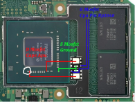
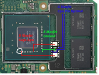
Hello, I will try soldering mosfets without flex cable for picofly mod after mosfets come. But I did not know why sometimes on schema there is one mosfet and on the others 2 mosfets. Should I use two IRFHS8342TRPBF or just one is sufficient? Whats the difference when using two mosfets? Also when using 2 mosfets I noticed two "G Mosfet" https://gbatemp.net/attachments/marikodual-mosfet-jpg.363515/ https://gbatemp.net/attachments/marikodual-mosfet-jpg.363515/ going to CPU pin of RP2040 - Connecting just one is sufficient? Or do I need to connect two of these points to the same pin of RP2040?
Hello, I will try soldering mosfets without flex cable for picofly mod after mosfets come. But I did not know why sometimes on schema there is one mosfet and on the others 2 mosfets. Should I use two IRFHS8342TRPBF or just one is sufficient? Whats the difference when using two mosfets? Also when using 2 mosfets I noticed two "G Mosfet" https://gbatemp.net/attachments/marikodual-mosfet-jpg.363515/ https://gbatemp.net/attachments/marikodual-mosfet-jpg.363515/ going to CPU pin of RP2040 - Connecting just one is sufficient? Or do I need to connect two of these points to the same pin of RP2040?
One is enough, just make sure to use thick enough wire from mosfet to cap, at least 0.2mm.
thank you, but why most of the people uses 2 mosfets? Whats the benefit of doing so?One is enough, just make sure to use thick enough wire from mosfet to cap, at least 0.2mm.
thank you, but why most of the people uses 2 mosfets? Whats the benefit of doing so?
Some people have had problems with only using one and got it working when using two. I'm not certain if the number of mosfets has been the actual issue though - I think it's more likely that the first one just wasn't working properly. Anyway, you can always test with one and add another if the rp2040 gives you cyan light.
Theoretically one mosfet is able to handle the current, people have been using two to make it easier to connect to both caps.
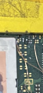
congrats your switch is booting into RCM mode. /s (dont worry I've done the same)Sorry can anyone help meI broke a pin at the CMD point, now the switch won't turn on. Is there anything I can do to save the situation?
The only way to get it to work is to reconnect the trace which goes off on the red line basically, 2-3 layers deep
you can check the board scans here
but I would recommend a professional to repair it
congrats your switch is booting into RCM mode. /s (dont worry I've done the same)
The only way to get it to work is to reconnect the trace which goes off on the red line basically, 2-3 layers deep
View attachment 365894
you can check the board scans here
but I would recommend a professional to repair it
Thank you very much for help me ^-^! Can I solder the wire in the left pad to the left part of this instead?
I killed this pico later, when unsuccessfully tried to put USB back. This method is ok and pico working good even without USB traces.No offense but seeing how you butchered those poor traces on pico does not make your opinion valid to not use hot air gun
View attachment 365761
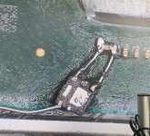
so i manage to solder mosfet to wire (its crazy hard)
basicly, i make their legs....
cuz i dont wanted the wire came off, im gonna use uv mask....
but...
how to use this uv mask ???
i never try use them ?
should i use brush or toothpick ?
how to dry them fast ? without uv light ? ( idont have uv light)

basicly, i make their legs....
cuz i dont wanted the wire came off, im gonna use uv mask....
but...
how to use this uv mask ???
i never try use them ?
should i use brush or toothpick ?
how to dry them fast ? without uv light ? ( idont have uv light)
Use a toothpick as it is better to handle. You can get a UV light bulb for 50 cents to your nearest electonic store.so i manage to solder mosfet to wire (its crazy hard)
basicly, i make their legs....
cuz i dont wanted the wire came off, im gonna use uv mask....
but...
how to use this uv mask ???
i never try use them ?
should i use brush or toothpick ?
how to dry them fast ? without uv light ? ( idont have uv light)
View attachment 365903
Yes, but the other cap shouldn't show continuity
I cant see anything wrong with those mosfets as far as the size is concerned. These are very tiny packages that should fit beside the APU die. Check these pics from my install. You will definately need a good microscope.@Phantomas77
am i bought the wrong mosfet ?
my mosfet sooo tiny ???
i cant even read the text hehehehhe lol
View attachment 365515
View attachment 365516
View attachment 365517
ant-man help!!
Post automatically merged:
I use 380C with a T12 soldering station. High temps quickly melt the tin without burning components through low temps prologed contact...For the mosfet only soldering iron. To be precise solder station, to target precisely the temperature. The difficult one is melting the tin onto the caps. Maybe the caps goes to heat sink or high temp tin. Its difficult to blend (melted) with our tin. Normally i use 300C, for this kind of work, i increse to 350C, yet still its not that good enough to melt it. Increase it more, i worry to ripped the pad.
I read on previous comment someone use 396C to solder the S pad on right bottom.
Attachments
yes, I looked at another board that I have and I saw that it does not give continuity, so I suppose that the other capacitor may be shorted, since it is very clean, and removing the other capacitor that shows continuity would be too much, I mean, leaving the processor without 2 capacitors, that's a lot, right?Yes, but the other cap shouldn't show continuity
Use sunlightso i manage to solder mosfet to wire (its crazy hard)
basicly, i make their legs....
cuz i dont wanted the wire came off, im gonna use uv mask....
but...
how to use this uv mask ???
i never try use them ?
should i use brush or toothpick ?
如何快速干燥它们?没有紫外线?(没有紫外线)
View attachment 365903
Similar threads
- Replies
- 4
- Views
- 2K
- Replies
- 2
- Views
- 668
- Replies
- 42
- Views
- 7K
Site & Scene News
New Hot Discussed
-
-
30K views
New static recompiler tool N64Recomp aims to seamlessly modernize N64 games
As each year passes, retro games become harder and harder to play, as the physical media begins to fall apart and becomes more difficult and expensive to obtain. The... -
26K views
Nintendo officially confirms Switch successor console, announces Nintendo Direct for next month
While rumors had been floating about rampantly as to the future plans of Nintendo, the President of the company, Shuntaro Furukawa, made a brief statement confirming... -
24K views
TheFloW releases new PPPwn kernel exploit for PS4, works on firmware 11.00
TheFlow has done it again--a new kernel exploit has been released for PlayStation 4 consoles. This latest exploit is called PPPwn, and works on PlayStation 4 systems... -
23K views
Name the Switch successor: what should Nintendo call its new console?
Nintendo has officially announced that a successor to the beloved Switch console is on the horizon. As we eagerly anticipate what innovations this new device will... -
14K views
DOOM has been ported to the retro game console in Persona 5 Royal
DOOM is well-known for being ported to basically every device with some kind of input, and that list now includes the old retro game console in Persona 5 Royal... -
12K views
Delta emulator for iOS will support iPad devices in its next update
With just a couple weeks after its initial release in the App Store, the Delta emulator for iOS was received with great success, after Apple loosened up its rules in...by ShadowOne333 36 -
12K views
Mario Builder 64 is the N64's answer to Super Mario Maker
With the vast success of Super Mario Maker and its Switch sequel Super Mario Maker 2, Nintendo fans have long been calling for "Maker" titles for other iconic genres... -
12K views
Anbernic reveals the RG35XXSP, a GBA SP-inspired retro handheld
Retro handheld manufacturer Anbernic has revealed its first clamshell device: the Anbernic RG35XXSP. As the suffix indicates, this handheld's design is inspired by... -
11K views
"Nintendo World Championships: NES Edition", a new NES Remix-like game, launching July 18th
After rumour got out about an upcoming NES Edition release for the famed Nintendo World Championships, Nintendo has officially unveiled the new game, titled "Nintendo...by ShadowOne333 78 -
11K views
Microsoft is closing down several gaming studios, including Tango Gameworks and Arkane Austin
The number of layoffs and cuts in the videogame industry sadly continue to grow, with the latest huge layoffs coming from Microsoft, due to what MIcrosoft calls a...by ShadowOne333 65
-
-
-
310 replies
Name the Switch successor: what should Nintendo call its new console?
Nintendo has officially announced that a successor to the beloved Switch console is on the horizon. As we eagerly anticipate what innovations this new device will...by Costello -
233 replies
Nintendo officially confirms Switch successor console, announces Nintendo Direct for next month
While rumors had been floating about rampantly as to the future plans of Nintendo, the President of the company, Shuntaro Furukawa, made a brief statement confirming...by Chary -
133 replies
New static recompiler tool N64Recomp aims to seamlessly modernize N64 games
As each year passes, retro games become harder and harder to play, as the physical media begins to fall apart and becomes more difficult and expensive to obtain. The...by Chary -
96 replies
Ubisoft reveals 'Assassin's Creed Shadows' which is set to launch later this year
Ubisoft has today officially revealed the next installment in the Assassin's Creed franchise: Assassin's Creed Shadows. This entry is set in late Sengoku-era Japan...by Prans -
88 replies
The Kingdom Hearts games are coming to Steam
After a little more than three years of exclusivity with the Epic Games Store, Square Enix has decided to bring their beloved Kingdom Hearts franchise to Steam. The...by Chary -
80 replies
TheFloW releases new PPPwn kernel exploit for PS4, works on firmware 11.00
TheFlow has done it again--a new kernel exploit has been released for PlayStation 4 consoles. This latest exploit is called PPPwn, and works on PlayStation 4 systems...by Chary -
78 replies
"Nintendo World Championships: NES Edition", a new NES Remix-like game, launching July 18th
After rumour got out about an upcoming NES Edition release for the famed Nintendo World Championships, Nintendo has officially unveiled the new game, titled "Nintendo...by ShadowOne333 -
71 replies
DOOM has been ported to the retro game console in Persona 5 Royal
DOOM is well-known for being ported to basically every device with some kind of input, and that list now includes the old retro game console in Persona 5 Royal...by relauby -
65 replies
Microsoft is closing down several gaming studios, including Tango Gameworks and Arkane Austin
The number of layoffs and cuts in the videogame industry sadly continue to grow, with the latest huge layoffs coming from Microsoft, due to what MIcrosoft calls a...by ShadowOne333 -
62 replies
Mario Builder 64 is the N64's answer to Super Mario Maker
With the vast success of Super Mario Maker and its Switch sequel Super Mario Maker 2, Nintendo fans have long been calling for "Maker" titles for other iconic genres...by Scarlet
-


