Hacking Hardware Picofly - a HWFLY switch modchip

Adran_Marit

Walküre's Hacker
Member
Joined
Oct 3, 2015
Messages
3,781
Trophies
1
Location
42*South
XP
4,557
Country
Australia
Github page is removed for the lock_pick rcm. Is product key important to restore and if we have the full nand backup and boot0/boot1 backup or it both require the product key to restore from backup?
To backup/restore a backup you don´t need keys, Hekate make all extractions.

you dont need the keys to restore, no, you do need the keys if you ever need to access your pc or rebuild your nand from scratch...
 

RiotRetroGaming

Well-Known Member
Newcomer
Joined
Mar 25, 2023
Messages
60
Trophies
0
Age
43
XP
164
Country
United Kingdom
Hi all,

Could somebody give me some pointers?
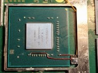
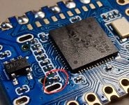
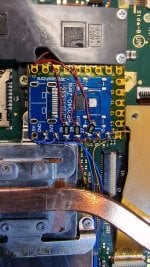
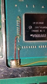
I have done a shed load of lites, v1, v2 and oleds without issue using APU flex cables... however, tonight I thought I would have a stab at the mosfet thing on a V2 on 16.0.3...

It glitched and went white, then blue, the the usual green.
This time it just booted OFW???

It does the same thing everytime, no 'NO SD CARD' prompt at all.
Odd? Included photos...

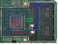
I have followed the following diagram too...


Thanks,
Ant
 

Attachments

  • Marikodual Mosfet.jpg
    Marikodual Mosfet.jpg
    111.8 KB · Views: 72
  • 20230516_232205.jpg
    20230516_232205.jpg
    2.4 MB · Views: 63
  • 20230516_232252.jpg
    20230516_232252.jpg
    3.3 MB · Views: 60
  • 20230516_232303.jpg
    20230516_232303.jpg
    3 MB · Views: 68

lightninjay

Well-Known Member
Member
Joined
Mar 28, 2023
Messages
560
Trophies
0
Age
31
XP
1,373
Country
United States
Hi all,

Could somebody give me some pointers?
I have done a shed load of lites, v1, v2 and oleds without issue using APU flex cables... however, tonight I thought I would have a stab at the mosfet thing on a V2 on 16.0.3...

It glitched and went white, then blue, the the usual green.
This time it just booted OFW???

It does the same thing everytime, no 'NO SD CARD' prompt at all.
Odd? Included photos...

I have followed the following diagram too...


Thanks,
Ant
It is likely Cyan underneath the kapton (instead of green), but if you have a spare rp2040-zero, or can attach wires to that pico to reflash it, you could try Rehius' most latest 2.7 firmware that would help you diagnose your issue with long and short flashes.

A bit of new features in the test version 2.70

- now it's only 3 colours: blue (glitching), white (flashing), yellow (error code). This was made to make possible pi pico debugging + get rid of RGB/GRB issues
Error codes list (= is long pulse, * is short pulse):

= USB flashing done

** RST is not connected
*= CMD is not connected
=* D0 is not connected
== CLK is not connected

=** eMMC init failure during glitch process
=*= CPU never reach BCT check, should not happen
==* CPU always reach BCT check (no glitch reaction, check mosfet)
=== Glitch attempt limit reached, cannot glitch

=*** eMMC init failure
=**= eMMC write failure - comparison failed
=*=* eMMC write failure - write failed
=*== eMMC test failure - read failed
==** eMMC read failed during firmware update
==*= BCT copy failed - write failure
===* BCT copy failed - comparison failure
==== BCT copy failed - read failure

The second major feature is CPU downvoltage. This might be useful when your MOSFET (or the wire) is not strong enough for the glitch. (do you remember the case where you press "RESET" on the rp2040 when joycon logo appears to make it working? that's it, system lowers CPU voltage)
Therefore you can solder two additional wires to the chip so it could lower the CPU voltage making the glitch easier. This is optional! only if you really need.

Waveshare rp2040: SDA=12, SCL=13
Pi Pico: SDA = 19, SCL = 20
XIAO 2040: SDA=3, SCL=4
ItayBitsy 2040: SDA = 18, SCL = 19

pinout for Mariko v2 board:
View attachment 371698

I have pinouts for Lite & OLED, but haven't tested it yet. You can easily track the i2c wires by yourself using board views here http://balika011.hu/switch/ (OLED here)

The firmware is in alpha stage, so use at your own risk
 

QuiTim

Well-Known Member
Member
Joined
Mar 30, 2023
Messages
754
Trophies
0
XP
1,154
Country
Albania
Hi all,

Could somebody give me some pointers?
I have done a shed load of lites, v1, v2 and oleds without issue using APU flex cables... however, tonight I thought I would have a stab at the mosfet thing on a V2 on 16.0.3...

It glitched and went white, then blue, the the usual green.
This time it just booted OFW???

It does the same thing everytime, no 'NO SD CARD' prompt at all.
Odd? Included photos...

I have followed the following diagram too...


Thanks,
Ant
Try using different 3v3 and GND (it worked in 2 cases)
Use thicker wire for 3v3 and GND.
Shorten all your wires (if possible)
 
  • Like
Reactions: jonesmith518

QuiTim

Well-Known Member
Member
Joined
Mar 30, 2023
Messages
754
Trophies
0
XP
1,154
Country
Albania
So, in the name of science (and mostly fun) I disassembled my Lite to try some other mosfet that I got today and to celebrate the release of fw2.7
The hard part (this time) was removing the previously installed SX Lite chip.
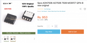
After removal and some cleaning I installed a single AON7506 mosfet which looks like it has the perfect package size (3x3) for these installations.
This time I used this new transparent (3 second curing) solder mask and it works as advertised.
I encountered a small hiccup while disassembling my picofly when I accidently wicked away a small capacitor on the bottom side of Pico.
Luckily I was able to retrieve it and solder it back (not very proud of that solder job but still…)
Also, the capacitor on top of the SDcard is damaged, but that was from my SX installation more than 3yrs ago. I don’t know what that cap does but I never had any issues with Switch, and even after removing the old chip and installing Pico everything works.
In the end everything worked out great so I didn’t get a chance to test the new “pulsing” error codes.
There are a couple of videos and photos attached where you can see flashing, first boot/glitch, 5th boot (after assembly), and also the assembled shield with Pico underneath (perfect fit).
Cheers
 

Attachments

  • 20230516_205943.jpg
    20230516_205943.jpg
    1 MB · Views: 63
  • 20230516_205407.jpg
    20230516_205407.jpg
    1.2 MB · Views: 75
  • 20230516_231036.jpg
    20230516_231036.jpg
    1 MB · Views: 63
  • 20230517_012216.jpg
    20230517_012216.jpg
    873.9 KB · Views: 60
  • 20230517_011333.jpg
    20230517_011333.jpg
    1.3 MB · Views: 65
  • 20230517_004940.jpg
    20230517_004940.jpg
    1.4 MB · Views: 54
  • 20230516_233200.jpg
    20230516_233200.jpg
    1.2 MB · Views: 61
  • 20230517_013840.mp4
    6.5 MB
  • 20230516_180937.mp4
    12.1 MB
  • 20230516_222743.mp4
    24.3 MB

rsilveira1991

Active Member
Newcomer
Joined
Apr 16, 2023
Messages
29
Trophies
0
Age
33
XP
93
Country
Brazil

FlowerFire

Well-Known Member
Newcomer
Joined
Mar 10, 2023
Messages
45
Trophies
0
XP
129
Country
United Kingdom
A bit of new features in the test version 2.70

- now it's only 3 colours: blue (glitching), white (flashing), yellow (error code). This was made to make possible pi pico debugging + get rid of RGB/GRB issues
Error codes list (= is long pulse, * is short pulse):

= USB flashing done

** RST is not connected
*= CMD is not connected
=* D0 is not connected
== CLK is not connected

=** eMMC init failure during glitch process
=*= CPU never reach BCT check, should not happen
==* CPU always reach BCT check (no glitch reaction, check mosfet)
=== Glitch attempt limit reached, cannot glitch

=*** eMMC init failure
=**= eMMC write failure - comparison failed
=*=* eMMC write failure - write failed
=*== eMMC test failure - read failed
==** eMMC read failed during firmware update
==*= BCT copy failed - write failure
===* BCT copy failed - comparison failure
==== BCT copy failed - read failure

The second major feature is CPU downvoltage. This might be useful when your MOSFET (or the wire) is not strong enough for the glitch. (do you remember the case where you press "RESET" on the rp2040 when joycon logo appears to make it working? that's it, system lowers CPU voltage)
Therefore you can solder two additional wires to the chip so it could lower the CPU voltage making the glitch easier. This is optional! only if you really need.

Waveshare rp2040: SDA=12, SCL=13
Pi Pico: SDA = 19, SCL = 20
XIAO 2040: SDA=3, SCL=4
ItayBitsy 2040: SDA = 18, SCL = 19

pinout for Mariko v2 board:
View attachment 371698

I have pinouts for Lite & OLED, but haven't tested it yet. You can easily track the i2c wires by yourself using board views here http://balika011.hu/switch/ (OLED here)

The firmware is in alpha stage, so use at your own risk
I installed picofly on a v1 and a v2 Switch and the v2 is a little bit slower when glitching (it never fails, though).
Can soldering the two optional wires help and make it faster or is this just for those who have problems with making it work at all?
 

abal1000x

Well-Known Member
Member
Joined
Jun 5, 2022
Messages
1,062
Trophies
0
XP
1,367
Country
Gaza Strip
A bit of new features in the test version 2.70

- now it's only 3 colours: blue (glitching), white (flashing), yellow (error code). This was made to make possible pi pico debugging + get rid of RGB/GRB issues
Error codes list (= is long pulse, * is short pulse):

= USB flashing done

** RST is not connected
*= CMD is not connected
=* D0 is not connected
== CLK is not connected

=** eMMC init failure during glitch process
=*= CPU never reach BCT check, should not happen
==* CPU always reach BCT check (no glitch reaction, check mosfet)
=== Glitch attempt limit reached, cannot glitch

=*** eMMC init failure
=**= eMMC write failure - comparison failed
=*=* eMMC write failure - write failed
=*== eMMC test failure - read failed
==** eMMC read failed during firmware update
==*= BCT copy failed - write failure
===* BCT copy failed - comparison failure
==== BCT copy failed - read failure

The second major feature is CPU downvoltage. This might be useful when your MOSFET (or the wire) is not strong enough for the glitch. (do you remember the case where you press "RESET" on the rp2040 when joycon logo appears to make it working? that's it, system lowers CPU voltage)
Therefore you can solder two additional wires to the chip so it could lower the CPU voltage making the glitch easier. This is optional! only if you really need.

Waveshare rp2040: SDA=12, SCL=13
Pi Pico: SDA = 19, SCL = 20
XIAO 2040: SDA=3, SCL=4
ItayBitsy 2040: SDA = 18, SCL = 19

pinout for Mariko v2 board:
View attachment 371698

I have pinouts for Lite & OLED, but haven't tested it yet. You can easily track the i2c wires by yourself using board views here http://balika011.hu/switch/ (OLED here)

The firmware is in alpha stage, so use at your own risk
I really love current feature.
Color code is difficult to differentiate. Different people different perception.
By changing the error code to pulse, its easier to recognize, and remove the misunderstanding between people.

I get this error
==* CPU always reach BCT check (no glitch reaction, check mosfet)

Then push reset while the joycon shows, the glitch worked, shows nosd.
Connecting the sda and scl using this reference point
lite_i2c.png


And connecting to xiao rp2040 with sda goes to pin 3 and scl goes to pin4 using this reference:
xiao_i2c.jpg


And it didn't work. I still need to push the reset button when the joycon logo shows. Did i mistakes on some step?
 
Last edited by abal1000x,
  • Like
Reactions: jonesmith518

bilalhassan341

Well-Known Member
Member
Joined
Apr 1, 2023
Messages
138
Trophies
0
XP
271
Country
United States
So, in the name of science (and mostly fun) I disassembled my Lite to try some other mosfet that I got today and to celebrate the release of fw2.7
The hard part (this time) was removing the previously installed SX Lite chip.
After removal and some cleaning I installed a single AON7506 mosfet which looks like it has the perfect package size (3x3) for these installations.
This time I used this new transparent (3 second curing) solder mask and it works as advertised.
I encountered a small hiccup while disassembling my picofly when I accidently wicked away a small capacitor on the bottom side of Pico.
Luckily I was able to retrieve it and solder it back (not very proud of that solder job but still…)
Also, the capacitor on top of the SDcard is damaged, but that was from my SX installation more than 3yrs ago. I don’t know what that cap does but I never had any issues with Switch, and even after removing the old chip and installing Pico everything works.
In the end everything worked out great so I didn’t get a chance to test the new “pulsing” error codes.
There are a couple of videos and photos attached where you can see flashing, first boot/glitch, 5th boot (after assembly), and also the assembled shield with Pico underneath (perfect fit).
Cheers
Is this the same mosfet which you used or not?. I want to order this because it is bigger and will be easy to handle while soldering.
 

Attachments

  • Screenshot 2023-05-17 at 10.54.35 AM.png
    Screenshot 2023-05-17 at 10.54.35 AM.png
    390.5 KB · Views: 63

cgtchy0412

Well-Known Member
Member
Joined
Apr 26, 2023
Messages
287
Trophies
0
Age
41
XP
432
Country
Indonesia
I really love current feature.
Color code is difficult to differentiate. Different people different perception.
By changing the error code to pulse, its easier to recognize, and remove the misunderstanding between people.

I get this error
==* CPU always reach BCT check (no glitch reaction, check mosfet)

Then push reset while the joycon shows, the glitch worked, shows nosd.
Connecting the sda and scl using this reference point
View attachment 371828

And connecting to xiao rp2040 with sda goes to pin 3 and scl goes to pin4 using this reference:
View attachment 371827

And it didn't work. I still need to push the reset button when the joycon logo shows. Did i mistakes on some step?
This is specific for this rp board or what ?, coz in pi pico there is no reset button.
 

agus

Active Member
Newcomer
Joined
Apr 15, 2016
Messages
41
Trophies
0
Age
37
XP
113
Country
Indonesia
can i get a preview of the hekate image on the picofly chip? I see on YouTube there are people who install picofly. but the initial view is hekate. not a pico image
 

Site & Scene News

Popular threads in this forum

General chit-chat
Help Users
    K3Nv2 @ K3Nv2: https://youtu.be/cKEFoR8kec0?si=ZyebV_OHR6dxXWCE