I installed the picofly using the method of just one mosfet on the back of the board, the other points I used from the PicoFlyGuideV.6.2 tutorial here on the forum, the same way I did it on another V2 switch that works normally. Would it be a case of redoing the installation or even replacing the picofly?
Try using OFW then write something to the microsd.
If its corrupted than its for sure the hardware (not from software such as hekate, atmosphere, etc).
I feel its more about hardware, like something is shorting the power line, consistently.
Check the cable, especially if you use enameled cable, on the edge. If its shorting the board.
SciresM answered that error 010041544d530000 is likely related to a malformed user-configuration ini file. https://github.com/Atmosphere-NX/Atmosphere/issues/1914
It could be an humand error, some editor leaving some invisible unicode junk or maybe you have some corruption on your card.
The user reporting the issue said he had to comment out the setting : power_menu_reboot_function
More people are having issues with this setting it seems.
Thanks for the link, I just read it and the problem reported is starting atmosphere, the fatal error in my case I can get around using the archive bit fix via Hekate. The big question is why are the games installed by DBI corrupting?
The card used passed the H2testw test without any problems
Try using OFW then write something to the microsd.
If its corrupted than its for sure the hardware (not from software such as hekate, atmosphere, etc).
I feel its more about hardware, like something is shorting the power line, consistently.
Check the cable, especially if you use enameled cable, on the edge. If its shorting the board.
Thanks, I'll do that test tomorrow.
And yes, I used enameled wire, I was very careful during the installation so as not to damage anything, but a short could happen, I'll check everything, I'll probably change the wiring to be sure
So, I installed a RP2040 (Aliexpress) in my patched V1 and I wondered if the RP2040 is defective or if I did something wrong installing it.
The RP2040 does not want to be flashed: It shows up on my PC and Chromebook as external drive but nothing happens when I copy the fw_2.73.uf2 to it. Not even when I hold the boot button while connecting it to my PC. Also, there is no LED activity at all on the RP2040.
I figured that maybe it has preinstalled FW so I went ahead to install in into my switch. Upon booting, the switch boots straight into OFW, and again, the RP2040 has no led activity.
Is this a case of a faulty RP2040 or is my installation not correct? I am assuming that if I incorrectly installed in my switch that the switch wouldn't even boot to OFW?
Are they all RP2040-zero or RP2040-tiny? Do they have the Waveshare logo? If the Picofly firmware is on them, the LED should flash whenever the RP2040 is powered on. Not likely all 4 are defective.
Otherwise, they might be clone boards, some of those come with who knows what resistor values, and the LED wired wrong.
Update: I just put a picofly in from a switch that is working and it booted up to the picofly logo (and led is working) so I assume it's not my soldering job. The RP2040 must be without firmware but I can't get them to flash.
Is there another way to flash these maybe (instead of copying the w_2.73.uf2 to it)?
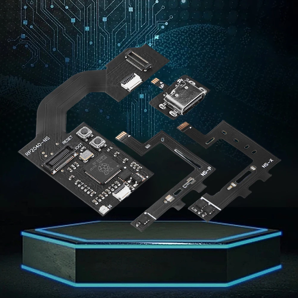
It's the board below:
Post automatically merged:
Update again: Seems the .uf2 was corrupt.... Though I did re-download it earlier, I did so again and now it worked.... Sorry for the confusion guys.... And thanks for your help.
if you look up sthetix on youtube he has a bunch of great video on how to do the install as well as a github with a bunch of how to with numerous different mod chip being install on all different models.
Hey guys , i recently installed two hwfly V6 on oled switch , one works perfectly, the other one is acting weird, it wont show any led light on the mod chip , and boot to official firmware only with no sign of detecting the mod chip , i tested the points sometimes 3.3v point give me 1.3v and sometimes show 0.933v and B show 1.5v or 1.8v other points are between normal range (0.5v to 0.9).
Any idea that might help me in the right direction?
Hi all, would like to ask for some guidance, have this OLED with SKHynix which has been driving me nuts..
My usual install procedure:
RP2040-Tiny FW2.75 + 47/100/100
eMMC reball with leaded solder + AWG42 enamel wire for DAT0
CPU flex with double MOSFET
AWG36 insulated wires for the rest of points + AWG30 for 3.3/GND
The console on first boot showed ** RST is not connected I reflowed RST wire on the chip and then **= No eMMC block 1 read (should not happen). I verified and reflowed all DATA wires. Then it started to glitch and successfully boot to NO SD card screen. I did some more restarts and it always booted to NO SD screen within usual time. So I disconnected battery, started to apply some kapton on top of the chip, connected battery back to check before assembly and than I got =* D0 is not connected.
If I unplug and plug back the battery connector, sometimes it boots to NO SD, if I unplug and plug it again, I get D0 error. What I've done so far without success: reflowed eMMC, tested with RP2040-Zero (47/100/100), reballed again eMMC with new DAT0 wire, flashed RP2040-zero with 2.73 FW. I continue to get DAT0 error or successfull "NO SD boot" when I uplug/plug battery connector.
Whenever it glitches, the Hekate shows no problems with eMMC speed (400MB/s) and OFW works. I've already backup the prodkeys and Boot0/Boot1 data.
Right now on RP2040-zero sometimes I don't see any light on power on (black screen as well) or sometimes it slightly blinks blue... Seems like a short or something? Already checked all the power and data wires.
Looking the error such as RST wire, then D0 error, then plug and unplug the battery.
Seems like theres common issue.
The RST might occured because the 3.3V power goes to rp2040 is not 3.3V.
The D0 error similar to RST, checking the voltage and outside of the normal voltage.
And again plug and unplug the battery might also affecting the 3.3V voltage goes to rp2040.
Maybe the first probe is checking the 3.3V voltage goes to the rp2040.
Thanks for your insight @abal1000x, I didn't have a chance to do anything and it's always a black screen now, no light on pico after power button press. Seems like I burned something... I uninstalled the chip and CPU flex, black screen persists and the board seems to be heating if I plug it with power supply.
Any idea where should I start? Will check the M92T and PI13USB for shorts now...
Do the console boot without the chip? If not check the 3.3v rail if it is shorted or not. If it is not shorted check the voltage when you plug the power cable in to see if the 3.3v rail give you 3.3v or not. If it is not then check your 3.3v regulator.
Update: I just put a picofly in from a switch that is working and it booted up to the picofly logo (and led is working) so I assume it's not my soldering job. The RP2040 must be without firmware but I can't get them to flash.
Is there another way to flash these maybe (instead of copying the w_2.73.uf2 to it)?
It's the board below:
Post automatically merged:
Update again: Seems the .uf2 was corrupt.... Though I did re-download it earlier, I did so again and now it worked.... Sorry for the confusion guys.... And thanks for your help.
Yup!! If I disconnect the cmd from Picofly I get the correct error "cmd isn't connected". If I measure from the top side of cmd resistor till the end of my wire, I get 4.7 KOhm
I get *== only when I disconnect clk and CPU, I've checked again both wires and diode readings, everything is normal like I used to get with the OLEDs that I've modded in the past
Sony made a shocking announcement today, revealing that the company plans to move away from physical game releases in the future. Citing claims of how the industry is...
After much speculation, a lot of which being caused by dbrand's unceremonious reveal of their Companion Cube casing, the Steam Machine is finally available to order...
Remember when you could get an Xbox Series S for $300? Those were the days. Microsoft has today announced the latest in their console price hikes, seeing their...
Since being decompiled Super Mario 64 has seen a considerable amount of interest. We've had multiple PC ports, but the efforts beyond that are really astounding. It's...
Happy June 15th! Well, this one was close enough. Atmosphere has been updated to add support for the latest Nintendo Switch firmware, 22.5.0. This means all of you...
The delays may be behind us, but the news isn't all good for Grand Theft Auto VI. Rockstar have today announced that pre-orders for the game will go live tomorrow, on...
It's that time again. Batten down the hatches and ride out the storm, because we've got another Switch update! And Switch 2, but that's somewhat less impactful given...
Last month we got confirmation of a new model of Switch 2 to better comply with upcoming EU regulations. With the legislation set to come into effect in February of...
The end has come for the PlayStation 3 and the PlayStation Vita. After supporting the PSN Store on the PS3 and PS Vita since 2006 and 2011 respectively, Sony has...
With many a fantastic port under their belts, Harbour Masters return with a brand new project dubbed Lighthouse. Set to release next month, it'll once again throw...
Sony made a shocking announcement today, revealing that the company plans to move away from physical game releases in the future. Citing claims of how the industry is...
After much speculation, a lot of which being caused by dbrand's unceremonious reveal of their Companion Cube casing, the Steam Machine is finally available to order...
Remember when you could get an Xbox Series S for $300? Those were the days. Microsoft has today announced the latest in their console price hikes, seeing their...
The delays may be behind us, but the news isn't all good for Grand Theft Auto VI. Rockstar have today announced that pre-orders for the game will go live tomorrow, on...
Last month we got confirmation of a new model of Switch 2 to better comply with upcoming EU regulations. With the legislation set to come into effect in February of...
The end has come for the PlayStation 3 and the PlayStation Vita. After supporting the PSN Store on the PS3 and PS Vita since 2006 and 2011 respectively, Sony has...
Tired of waiting for Game Freak to bring Pokemon Emerald to modern platforms? We've got you covered with a brand new port in the works. Currently available on GitHub...
Since being decompiled Super Mario 64 has seen a considerable amount of interest. We've had multiple PC ports, but the efforts beyond that are really astounding. It's...
Apple have today announced price increases, primarily focused on their MacBook and iPad lines. These increases have already come into effect, with both prices and the...
It's that time again. Batten down the hatches and ride out the storm, because we've got another Switch update! And Switch 2, but that's somewhat less impactful given...


 I enjoyed the chip as much as you do. Perfect placement for every device.


