Hacking Hardware Picofly - a HWFLY switch modchip

thesjaakspoiler

Well-Known Member
Member
Joined
Nov 20, 2018
Messages
981
Trophies
0
Age
124
XP
1,491
Country
Afghanistan
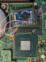
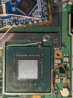
Hey guys, Im new to this and I modded an oled with picofly, everything was running fine for weeks but I left it on the dock overnight and I was greeted by a bsod, followed after these images. The console was warm in the morning.
The No SD card screen from the picofly can be seen without artifacts, but anything past that has artifacts in the screen and does not go past the hekate loading screen.
Edit:
Booting with +- shows bsod again.
What do you guys think the issue could be? Ram or CPU reballing? Anything else worth trying?
Looks more like you have some issue with the screen, the ribbon cable or the connector.
Might the ribbon cable be just misaligned?
To me it sounds unlikely that the cpu would get this far if the ram somehow was having issues.
What happens if you put the Switch in the dock?
 

Carquinca

Member
Newcomer
Joined
Mar 31, 2024
Messages
9
Trophies
0
Age
21
XP
21
Country
Spain
Looks more like you have some issue with the screen, the ribbon cable or the connector.
Might the ribbon cable be just misaligned?
To me it sounds unlikely that the cpu would get this far if the ram somehow was having issues.
What happens if you put the Switch in the dock?
Get blue screen bombed if I try to go to the ofw with +- and the hekate with artifacts if i just slot it in.
Well yeah I was thinking that because its showing image it might be due to a faulty ram module, because the No SD card screen from picofly does not have artifacts
 

superxoi

Well-Known Member
Member
Joined
May 8, 2020
Messages
159
Trophies
0
Age
32
XP
830
Country
Vietnam
Hey guys, Im new to this and I modded an oled with picofly, everything was running fine for weeks but I left it on the dock overnight and I was greeted by a bsod, followed after these images. The console was warm in the morning.
The No SD card screen from the picofly can be seen without artifacts, but anything past that has artifacts in the screen and does not go past the hekate loading screen.
Edit:
Booting with +- shows bsod again.
What do you guys think the issue could be? Ram or CPU reballing? Anything else worth trying?
I have fixed this case one. The console sometime could boot to hekate and freezed at some point sometime showed crashing image. My case was dram . you have to take a gamble between cpu and dram good luck.
 

Endracion

Well-Known Member
Newcomer
Joined
May 16, 2008
Messages
56
Trophies
1
XP
229
Country
Canada
Man, I'm really confused, I've done a bunch of rear mosfet installs without a problem.

Today I wanted to try the full front install without having to remove the motherboard, so I basically did this:
1713078427955.png


At first I was getting the ==* error, so I thought it might be the mosfet, so I desoldered it, and then the wires as well because the gate and drain were also grounded/shorted. After I removed everything, I checked all of the caps in the red rectangle and they're all shorted? I don't think that's normal? But the switch boots normally in OFW, really confused. I place the leads of the multimeter on each side of the cap or on the ground shield and they're all connected, did I overheat them somehow and they're all bad now? I still don't get how it boots to OFW - or is something else wrong? To be clear, nothing physically looks wrong, nothing's missing and it was well cleaned up.

EDIT: Found this video where it's basically exactly like what he tests, but I see nobody chimed in with a solution:
 
Last edited by Endracion,

abal1000x

Well-Known Member
Member
Joined
Jun 5, 2022
Messages
1,062
Trophies
0
XP
1,367
Country
Gaza Strip
Man, I'm really confused, I've done a bunch of rear mosfet installs without a problem.

Today I wanted to try the full front install without having to remove the motherboard, so I basically did this:
View attachment 431605

At first I was getting the ==* error, so I thought it might be the mosfet, so I desoldered it, and then the wires as well because the gate and drain were also grounded/shorted. After I removed everything, I checked all of the caps in the red rectangle and they're all shorted? I don't think that's normal? But the switch boots normally in OFW, really confused. I place the leads of the multimeter on each side of the cap or on the ground shield and they're all connected, did I overheat them somehow and they're all bad now? I still don't get how it boots to OFW - or is something else wrong? To be clear, nothing physically looks wrong, nothing's missing and it was well cleaned up.

EDIT: Found this video where it's basically exactly like what he tests, but I see nobody chimed in with a solution:

Its normal. Its not totally zero ohm, theres ohm around 3-5ohms, in my multimeter.
 

Endracion

Well-Known Member
Newcomer
Joined
May 16, 2008
Messages
56
Trophies
1
XP
229
Country
Canada
Its normal. Its not totally zero ohm, theres ohm around 3-5ohms, in my multimeter.
With some further reading that's not at 4am, I do understand they're just so low the multimeter picks it up as continuity, but it's not, so thanks for that. It must be something else then.

Could it be that the wire I used that goes to the caps is too thin? I could try a thicker gauge?

The diode readings were good as far as I know. I'd like to check for the mosfet being broken, but it seems to work as far as I can tell.
 
Last edited by Endracion,

TankedThomas

Well-Known Member
Member
Joined
May 5, 2009
Messages
624
Trophies
1
Location
New Zealand
XP
561
Country
New Zealand
Sorry if this has been answered but I've searched a bunch over the past few weeks, and this thread is super-long so it's hard to find any definitive answers.

I recently got a Switch Lite and want to install a chip into it. My only real issue is what chip to use. I'd rather avoid soldering SMD caps straight to an RP2040 (doesn't seem very robust) but there don't seem to be any good custom PCBs.
I figured the AliExpress route might be an option but there are so many different versions there (and apparently some use knock-off RP2040s, despite being a cheap and ubiquitous chip).

Does anyone have any solid recommendations? I've got no issue having a PCB manufactured and populating it, so if there's a good custom option I haven't seen (only one I've found is "Reckless Picofly" which seems to be incomplete anyway), I'm down for that.
Short of that, I guess I could make my own in KiCAD, but I'm not familiar enough with the RP2040 hardware to do a great job at that.
 

Endracion

Well-Known Member
Newcomer
Joined
May 16, 2008
Messages
56
Trophies
1
XP
229
Country
Canada
Sorry if this has been answered but I've searched a bunch over the past few weeks, and this thread is super-long so it's hard to find any definitive answers.

I recently got a Switch Lite and want to install a chip into it. My only real issue is what chip to use. I'd rather avoid soldering SMD caps straight to an RP2040 (doesn't seem very robust) but there don't seem to be any good custom PCBs.
I figured the AliExpress route might be an option but there are so many different versions there (and apparently some use knock-off RP2040s, despite being a cheap and ubiquitous chip).

Does anyone have any solid recommendations? I've got no issue having a PCB manufactured and populating it, so if there's a good custom option I haven't seen (only one I've found is "Reckless Picofly" which seems to be incomplete anyway), I'm down for that.
Short of that, I guess I could make my own in KiCAD, but I'm not familiar enough with the RP2040 hardware to do a great job at that.
Did you check the guide? The recommended RP2040-Tiny from Waveshare doesn't require anything additional.
The custom way, there was one recently, but also many others: https://gbatemp.net/threads/picofly-a-hwfly-switch-modchip.622701/page-750#post-10367725
 
  • Like
Reactions: TankedThomas

TankedThomas

Well-Known Member
Member
Joined
May 5, 2009
Messages
624
Trophies
1
Location
New Zealand
XP
561
Country
New Zealand
Did you check the guide? The recommended RP2040-Tiny from Waveshare doesn't require anything additional.
The custom way, there was one recently, but also many others: https://gbatemp.net/threads/picofly-a-hwfly-switch-modchip.622701/page-750#post-10367725
I did. There are so many options that it gets confusing though. And so many guides. So I hope I checked the right guide (EDIT: I did, must have just skimmed it). The modern GBAtemp layout is a disaster to navigate, so that doesn't help.
I'll have a look for the info on the RP2040-Tiny though. Sounds like the way to go, since it seems like having USB makes it more convenient to flash, though I might use the custom Tinyfly board just because it's tailor-made. Thanks.
 

abal1000x

Well-Known Member
Member
Joined
Jun 5, 2022
Messages
1,062
Trophies
0
XP
1,367
Country
Gaza Strip
Is it normal for the gate to have continuity with the ground, rather for it to beep as well? Or it's the same thing and it's just low ohms? The diode readings were good as far as I know. Would I just need to check for the mosfet being broken?
Gate should not have continuity with the ground, it should not beep.
I am still on travelling, can't confirm this.

Reading from this thread, i think theres bad quality mosfet.
Luckily i have not meet with those bad quality mosfet.

For me, the problem always lays on the conductivity of conductor D and S.
Since the D and S will be shorted, it need good conductivity, means bigger conductor (big diam), and good material (copper).
For the S is easy to make it big, since its connected to the GND. Simply solder it to the big aluminium casing.

For the D thats gonna be tricky.
That is why i made it so that theres 2 branch of conductor that connect the D.
https://gbatemp.net/threads/picofly-a-hwfly-switch-modchip.622701/page-481#post-10179786
 

Endracion

Well-Known Member
Newcomer
Joined
May 16, 2008
Messages
56
Trophies
1
XP
229
Country
Canada
Gate should not have continuity with the ground, it should not beep.
I am still on travelling, can't confirm this.

Reading from this thread, i think theres bad quality mosfet.
Luckily i have not meet with those bad quality mosfet.

For me, the problem always lays on the conductivity of conductor D and S.
Since the D and S will be shorted, it need good conductivity, means bigger conductor (big diam), and good material (copper).
For the S is easy to make it big, since its connected to the GND. Simply solder it to the big aluminium casing.

For the D thats gonna be tricky.
That is why i made it so that theres 2 branch of conductor that connect the D.
https://gbatemp.net/threads/picofly-a-hwfly-switch-modchip.622701/page-481#post-10179786
Here's what it looks like, I used 0.15 on what I assume is D. I'm going to try larger gauge on all and double up like you show, thanks for that tip, I even had it saved to look into.

Post automatically merged:

Here's what it looks like, I used 0.15 on what I assume is D. I'm going to try larger gauge on all and double up like you show, thanks for that tip, I even had it saved to look into.
Man, unfortunately, same thing here, should I try an even thicker gauge?

What I was saying about the gate have continuity with ground was wrong, it doesn't, I think I was just hitting the shield due to the position. I've checked it again on the RP2040 and it's fine. What does beep is D, but that's because of the low ohm reading like the caps, which seems to be normal.

EDIT: OK! I swapped the S wire as well for thicker gauge and made the blob on the shield larger, seems to have worked! I'll keep in mind to use everything thicker here in the future, thanks so much for the tips!

EDIT2: Darn it, I cleaned it up and now it's just flashing blue as if it's training, but unable to get to no sd screen after the first time.
 

Attachments

  • PXL_20240414_143256692.jpg
    PXL_20240414_143256692.jpg
    3 MB · Views: 5
  • PXL_20240414_144418278.jpg
    PXL_20240414_144418278.jpg
    2.9 MB · Views: 6
Last edited by Endracion,

abal1000x

Well-Known Member
Member
Joined
Jun 5, 2022
Messages
1,062
Trophies
0
XP
1,367
Country
Gaza Strip
Here's what it looks like, I used 0.15 on what I assume is D. I'm going to try larger gauge on all and double up like you show, thanks for that tip, I even had it saved to look into.

Post automatically merged:


Man, unfortunately, same thing here, should I try an even thicker gauge?

What I was saying about the gate have continuity with ground was wrong, it doesn't, I think I was just hitting the shield due to the position. I've checked it again on the RP2040 and it's fine. What does beep is D, but that's because of the low ohm reading like the caps, which seems to be normal.
The D looks good, only the S/GND seems need bigger diam.
 

Danook28

Well-Known Member
Member
Joined
Jul 17, 2018
Messages
495
Trophies
0
Age
34
XP
1,030
Country
Oman
In the system file in nand backup /content /(1)placehld and (2)registered different firmware
First one is 8.0.0
Next one is 7.0.1
Unpatched V1 (2018)
Is it normal in V1 console????
 

RoXuS

Member
Newcomer
Joined
Feb 26, 2024
Messages
11
Trophies
0
Age
36
XP
33
Country
France
Someone know if I can use wires on v6s cable (for OLED / Lite / V2 model) but on a v1 switch ? Without issue ?

For the left capacitor, the top of the capacitor on the right part of the flex cable.
For the right capacitor, the top of the capacitor on the left part of the flex cable.

PXL_20240414_194037857.jpg
 

Danook28

Well-Known Member
Member
Joined
Jul 17, 2018
Messages
495
Trophies
0
Age
34
XP
1,030
Country
Oman
Someone know if I can use wires on v6s cable (for OLED / Lite / V2 model) but on a v1 switch ? Without issue ?

For the left capacitor, the top of the capacitor on the right part of the flex cable.
For the right capacitor, the top of the capacitor on the left part of the flex cable.

View attachment 431754
On gnd on flex must beep on multimeter to know that on cap must use it for safe way so on this V1 cap the gnd is under S up is D... 👏
Screenshot_٢٠٢٤٠٤١٥_٠٠٠٢٠٢_com.android.gallery3d.png
 
  • Like
Reactions: twins333

RoXuS

Member
Newcomer
Joined
Feb 26, 2024
Messages
11
Trophies
0
Age
36
XP
33
Country
France
thank you both, it’s very clear.
Post automatically merged:

Done and works like a charm, a little "heavy" with wires and kapton, the shield is a little distorted but everything works.

For the next V1, I will use a v1 flex cable it's more clean install...
 
Last edited by RoXuS,

thesjaakspoiler

Well-Known Member
Member
Joined
Nov 20, 2018
Messages
981
Trophies
0
Age
124
XP
1,491
Country
Afghanistan
Get blue screen bombed if I try to go to the ofw with +- and the hekate with artifacts if i just slot it in.
Well yeah I was thinking that because its showing image it might be due to a faulty ram module, because the No SD card screen from picofly does not have artifacts
Sorry, I missed that 'No SD card' screen part in your first post.
The No SD card screen with artifacts would indeed suggest that the TFT might be fine.
But I haven't seen much posts here that mention issues with the ram chips.
The usually don't have as much stress from heat as the tegra mpu.
I noted some post where a user mentioned that the tegra mpu was the cause of his blue screen problems.
He applied some moderate pressure to the mpu and found that in that case the switch would boot normally.
After having it reballed his problems went away.
You could try doing the same for the ram modules when in doubt.
 

Site & Scene News

Popular threads in this forum

General chit-chat
Help Users
  • No one is chatting at the moment.
  • Xdqwerty @ Xdqwerty:
    good night
  • BakerMan @ BakerMan:
    as to you
  • K3Nv2 @ K3Nv2:
    How do you know if the night will be good when you're asleep
  • BakerMan @ BakerMan:
    because i didn't say i was asleep
  • BakerMan @ BakerMan:
    i said i was sleeping...
  • BakerMan @ BakerMan:
    sleeping with uremum
  • K3Nv2 @ K3Nv2:
    Even my mum slept on that uremum
  • TwoSpikedHands @ TwoSpikedHands:
    yall im torn... ive been hacking away at tales of phantasia GBA (the USA version) and have so many documents of reverse engineering i've done
  • TwoSpikedHands @ TwoSpikedHands:
    I just found out that the EU version is better in literally every way, better sound quality, better lighting, and there's even a patch someone made to make the text look nicer
  • TwoSpikedHands @ TwoSpikedHands:
    Do I restart now using what i've learned on the EU version since it's a better overall experience? or do I continue with the US version since that is what ive been using, and if someone decides to play my hack, it would most likely be that version?
  • Sicklyboy @ Sicklyboy:
    @TwoSpikedHands, I'll preface this with the fact that I know nothing about the game, but, I think it depends on what your goals are. Are you trying to make a definitive version of the game? You may want to refocus your efforts on the EU version then. Or, are you trying to make a better US version? In which case, the only way to make a better US version is to keep on plugging away at that one ;)
  • Sicklyboy @ Sicklyboy:
    I'm not familiar with the technicalities of the differences between the two versions, but I'm wondering if at least some of those differences are things that you could port over to the US version in your patch without having to include copyrighted assets from the EU version
  • TwoSpikedHands @ TwoSpikedHands:
    @Sicklyboy I am wanting to fully change the game and bend it to my will lol. I would like to eventually have the ability to add more characters, enemies, even have a completely different story if i wanted. I already have the ability to change the tilemaps in the US version, so I can basically make my own map and warp to it in game - so I'm pretty far into it!
  • TwoSpikedHands @ TwoSpikedHands:
    I really would like to make a hack that I would enjoy playing, and maybe other people would too. swapping to the EU version would also mean my US friends could not legally play it
  • TwoSpikedHands @ TwoSpikedHands:
    I am definitely considering porting over some of the EU features without using the actual ROM itself, tbh that would probably be the best way to go about it... but i'm sad that the voice acting is so.... not good on the US version. May not be a way around that though
  • TwoSpikedHands @ TwoSpikedHands:
    I appreciate the insight!
  • The Real Jdbye @ The Real Jdbye:
    @TwoSpikedHands just switch, all the knowledge you learned still applies and most of the code and assets should be the same anyway
  • The Real Jdbye @ The Real Jdbye:
    and realistically they wouldn't

    be able to play it legally anyway since they need a ROM and they probably don't have the means to dump it themselves
  • The Real Jdbye @ The Real Jdbye:
    why the shit does the shitbox randomly insert newlines in my messages
  • Veho @ Veho:
    It does that when I edit a post.
  • Veho @ Veho:
    It inserts a newline in a random spot.
  • The Real Jdbye @ The Real Jdbye:
    never had that i don't think
    The Real Jdbye @ The Real Jdbye: never had that i don't think