Sure. I’ll post the git repo once all test are done. I’m making a small revision at the moment about the size and some extra pads.can you share Gerber file?
You are using an out of date browser. It may not display this or other websites correctly.
You should upgrade or use an alternative browser.
You should upgrade or use an alternative browser.
Staff Posts
Recent threadmarks
sharing files
Important Posts
Recent threadmarks
Firmwaresgood job,Sure. I’ll post the git repo once all test are done. I’m making a small revision at the moment about the size and some extra pads.
it would be nice if you add extra pad for led DIN, so if someone need to connect it to switch lite led
D = 1.310 has incorrect reading it should be between 0.400 to 0.800Does anyone know what the correct diode readings for a switch lite are?
Are these in the ballpark?(Meassured with GND on USB port)
3v = 0.748
C = 0.645
A = 0.545
D = 1.310
B = 1.145
GND = 0.05
Thx, yes actually just double checked D just now and resoldered . It's now 0.492VD = 1.310 has incorrect reading it should be between 0.400 to 0.800
I tried restoring my nand through eMMC RAW GPP and when it finished it said, "Your eMMC is initialized in slower mode! This might mean hardware issues!" When I check eMMC info I see Read/Write fails: 2. I also tried another Switches NAND and had the same problem, but with 3 errors instead of 2. There must be something wrong with the mod chip itself or maybe something else went wrong in the Switch?
100Ω on dat0?I tried restoring my nand through eMMC RAW GPP and when it finished it said, "Your eMMC is initialized in slower mode! This might mean hardware issues!" When I check eMMC info I see Read/Write fails: 2. I also tried another Switches NAND and had the same problem, but with 3 errors instead of 2. There must be something wrong with the mod chip itself or maybe something else went wrong in the Switch?
I tested dat0 at nearly 200Ω in circuit. One image I found shows that it should be 250Ω. The clk was tested as a short so I replaced it with a 47Ω resistor but in circuit it tests at 41Ω. Should I replace dat0 with a 100Ω resistor?100Ω on dat0?
I tested dat0 at nearly 200Ω in circuit. One image I found shows that it should be 250Ω. The clk was tested as a short so I replaced it with a 47Ω resistor but in circuit it tests at 41Ω. Should I replace dat0 with a 100Ω resistor? View attachment 422642
Throw it out and get an rp2040-tiny or zero instead. You know, the kind of chips that are actually supported in this thread
Your own Picofly look even better then the originalUpdate from my custom pcb design:
I received the custom pcb I made for rp2040, assembled all components and tested. It works great! It seems faster in glitching also about 2sec consistent.
Edit:
Each custom pcb and all components costs about less than $2 only.
You mean this one? Isn't it the same thing as I have but in a different form factor? Which thread would be for my type of mod chip then?Throw it out and get an rp2040-tiny or zero instead. You know, the kind of chips that are actually supported in this thread
You mean this one? Isn't it the same thing as I have but in a different form factor? Which thread would be for my type of mod chip then?
Yes, that's the one. It's almost the same thing but without an undocumented-and-horrible-quality pcb. Plenty of issues keep arising with the chinese clone boards that don't happen with rp2040-zero or tiny and it's not in the interest of this thread to discuss those issues here. Here are a few suitable threads for your purpose:
https://gbatemp.net/threads/hwfly-shaped-picofly-boards-start-shipping-in-china.632179/
https://gbatemp.net/threads/error-2002-3540-on-a-freshly-modded-switch.639602/
https://gbatemp.net/threads/picofly-hwfly-clone-help.649060/
https://gbatemp.net/threads/picofly-switch-error-code-2002-3539-in-ofw-17-0-0-and-17-0-1.646223/
Note that the rp2040-zero comes without resistors, and you should attach 100 ohm to dat0, 100 ohm to cmd, and 47 ohm to clk by yourself. The best resistor size for the purpose is 0805. The rp2040-tiny comes with 47-ohm resistors preattached to those points, which works most of the time but sometimes is too weak (resulting in slow emmc) and you'd need to add additional 47 ohm resistors to dat0 and cmd in that case.
Late replay but yes, that was the idea.I tested dat0 at nearly 200Ω in circuit. One image I found shows that it should be 250Ω. The clk was tested as a short so I replaced it with a 47Ω resistor but in circuit it tests at 41Ω. Should I replace dat0 with a 100Ω resistor? View attachment 422642
Deeps already explained pretty much everything that needs to be explained. You can give it a shot a replace the resistors on your current "hwfly" but as deeps already said, you should go with rp2040 boards that are supported in this thread (and in the guide) since pretty much all possible issues with those boards have been discussed and resolved here already.
Cheers
How hard is it to install the RP2040-tiny?Late replay but yes, that was the idea.
Deeps already explained pretty much everything that needs to be explained. You can give it a shot a replace the resistors on your current "hwfly" but as deeps already said, you should go with rp2040 boards that are supported in this thread (and in the guide) since pretty much all possible issues with those boards have been discussed and resolved here already.
Cheers
Not much harder than the one you have. Mosfet soldering can be a bit tricky (if ypu want to do a bare mosfet directlty to APU)but you can use the flex cable that came with your hwfly which is a bit easier.How hard is it to install the RP2040-tiny?
You still have to solder the points on the board but you need to do that anyway so....
The up side is that you have 750 pagese on this thread where you have all the info that you might encounter during install.
Try to avoid using magnet (enameled) wire, if you don't have experience with it you might end up with cold joint or a short somewhere, use 36-40awg pfa or ptfe or silicone wire.
yes, i agree. 750 pages with precious information where you can learn from the mistakes and failures of other users and prevent the same mistakesNot much harder than the one you have. Mosfet soldering can be a bit tricky (if ypu want to do a bare mosfet directlty to APU)but you can use the flex cable that came with your hwfly which is a bit easier.
You still have to solder the points on the board but you need to do that anyway so....
The up side is that you have 750 pagese on this thread where you have all the info that you might encounter during install.
It beats waiting for Aliepress to send me another mod chip. This video does say a ribbon cable makes it easier. Do I still need mosfets if I reuse the cable? Is there a better instructional video to do this?Not much harder than the one you have. Mosfet soldering can be a bit tricky (if ypu want to do a bare mosfet directlty to APU)but you can use the flex cable that came with your hwfly which is a bit easier.
You still have to solder the points on the board but you need to do that anyway so....
The up side is that you have 750 pagese on this thread where you have all the info that you might encounter during install.
It beats waiting for Aliepress to send me another mod chip. This video does say a ribbon cable makes it easier. Do I still need mosfets if I reuse the cable? Is there a better instructional video to do this?
I would not follow this video, it complicates things too much. Just follow the guide from here and you are all set: https://gbatemp.net/download/a-definitive-picofly-install-guide.37968/download
And no, you don't need mosfet when you use flex cable (it already has 2 mosfets attached)
If that's the case the resistor is too low..change it with 47ohms or if you have rp2040 zero chip.just replace it..I tested the resistor and I'm reading 196ohms. It's the one where the green line goes to. The other ones in that image are reading 42ohms except for the clk 27 which reads a dead short. That's the blue one. Isn't that one also suppose to be 47ohms? I'm going by the image.
Tinyfly v2.0 - the layout is based on the well known rp2040-tiny from waveshare but made for switch.
1. All necessary pads are exposed and the LED DIN as well.
2. Resistors and capacitors are 0402 size for easier soldering
3. Default D0,CMD,CLK resistors are 100,100,47ohm respectively
I've attached here the gerber file and bom/pick and place files.
Updates:
Tinyfly v2.0.zip - Initial Release
Tinyfly v2.0b.zip - Added extra pads for GND and 3V3 line on the right side. Swapped CPU and RST at the bottom part. Some components are changed to basic parts if planning to fabricate using JLCPCB.
Tinyfly v2.0c.zip - Adjusted few and changed components to basic parts for cheaper fabrication.
Images:
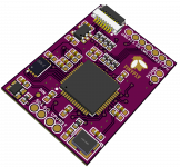
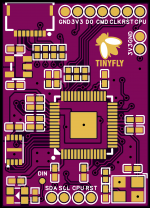
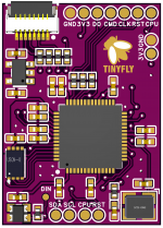

Component Mappings:
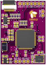
1. All necessary pads are exposed and the LED DIN as well.
2. Resistors and capacitors are 0402 size for easier soldering
3. Default D0,CMD,CLK resistors are 100,100,47ohm respectively
I've attached here the gerber file and bom/pick and place files.
Updates:
Tinyfly v2.0.zip - Initial Release
Tinyfly v2.0b.zip - Added extra pads for GND and 3V3 line on the right side. Swapped CPU and RST at the bottom part. Some components are changed to basic parts if planning to fabricate using JLCPCB.
Tinyfly v2.0c.zip - Adjusted few and changed components to basic parts for cheaper fabrication.
Images:


Component Mappings:

Attachments
Last edited by psycho-neon,
Similar threads
- Replies
- 4
- Views
- 2K
- Replies
- 2
- Views
- 573
- Replies
- 42
- Views
- 6K
Site & Scene News
New Hot Discussed
-
-
30K views
Nintendo Switch firmware update 18.0.1 has been released
A new Nintendo Switch firmware update is here. System software version 18.0.1 has been released. This update offers the typical stability features as all other... -
25K views
New static recompiler tool N64Recomp aims to seamlessly modernize N64 games
As each year passes, retro games become harder and harder to play, as the physical media begins to fall apart and becomes more difficult and expensive to obtain. The... -
24K views
Nintendo officially confirms Switch successor console, announces Nintendo Direct for next month
While rumors had been floating about rampantly as to the future plans of Nintendo, the President of the company, Shuntaro Furukawa, made a brief statement confirming... -
22K views
TheFloW releases new PPPwn kernel exploit for PS4, works on firmware 11.00
TheFlow has done it again--a new kernel exploit has been released for PlayStation 4 consoles. This latest exploit is called PPPwn, and works on PlayStation 4 systems... -
21K views
Nintendo takes down Gmod content from Steam's Workshop
Nintendo might just as well be a law firm more than a videogame company at this point in time, since they have yet again issued their now almost trademarked usual...by ShadowOne333 129 -
18K views
Name the Switch successor: what should Nintendo call its new console?
Nintendo has officially announced that a successor to the beloved Switch console is on the horizon. As we eagerly anticipate what innovations this new device will... -
16K views
A prototype of the original "The Legend of Zelda" for NES has been found and preserved
Another video game prototype has been found and preserved, and this time, it's none other than the game that spawned an entire franchise beloved by many, the very...by ShadowOne333 32 -
13K views
DOOM has been ported to the retro game console in Persona 5 Royal
DOOM is well-known for being ported to basically every device with some kind of input, and that list now includes the old retro game console in Persona 5 Royal... -
13K views
Nintendo Switch Online adds two more Nintendo 64 titles to its classic library
Two classic titles join the Nintendo Switch Online Expansion Pack game lineup. Available starting April 24th will be the motorcycle racing game Extreme G and another... -
11K views
AYANEO officially launches the Pocket S, its next-generation Android gaming handheld
Earlier this year, AYANEO revealed details of its next Android-based gaming handheld, the AYANEO Pocket S. However, the actual launch of the device was unknown; that...
-
-
-
280 replies
Name the Switch successor: what should Nintendo call its new console?
Nintendo has officially announced that a successor to the beloved Switch console is on the horizon. As we eagerly anticipate what innovations this new device will...by Costello -
232 replies
Nintendo officially confirms Switch successor console, announces Nintendo Direct for next month
While rumors had been floating about rampantly as to the future plans of Nintendo, the President of the company, Shuntaro Furukawa, made a brief statement confirming...by Chary -
130 replies
New static recompiler tool N64Recomp aims to seamlessly modernize N64 games
As each year passes, retro games become harder and harder to play, as the physical media begins to fall apart and becomes more difficult and expensive to obtain. The...by Chary -
129 replies
Nintendo takes down Gmod content from Steam's Workshop
Nintendo might just as well be a law firm more than a videogame company at this point in time, since they have yet again issued their now almost trademarked usual...by ShadowOne333 -
90 replies
Ubisoft reveals 'Assassin's Creed Shadows' which is set to launch later this year
Ubisoft has today officially revealed the next installment in the Assassin's Creed franchise: Assassin's Creed Shadows. This entry is set in late Sengoku-era Japan...by Prans -
82 replies
Nintendo Switch firmware update 18.0.1 has been released
A new Nintendo Switch firmware update is here. System software version 18.0.1 has been released. This update offers the typical stability features as all other...by Chary -
80 replies
TheFloW releases new PPPwn kernel exploit for PS4, works on firmware 11.00
TheFlow has done it again--a new kernel exploit has been released for PlayStation 4 consoles. This latest exploit is called PPPwn, and works on PlayStation 4 systems...by Chary -
78 replies
"Nintendo World Championships: NES Edition", a new NES Remix-like game, launching July 18th
After rumour got out about an upcoming NES Edition release for the famed Nintendo World Championships, Nintendo has officially unveiled the new game, titled "Nintendo...by ShadowOne333 -
71 replies
DOOM has been ported to the retro game console in Persona 5 Royal
DOOM is well-known for being ported to basically every device with some kind of input, and that list now includes the old retro game console in Persona 5 Royal...by relauby -
65 replies
Microsoft is closing down several gaming studios, including Tango Gameworks and Arkane Austin
The number of layoffs and cuts in the videogame industry sadly continue to grow, with the latest huge layoffs coming from Microsoft, due to what MIcrosoft calls a...by ShadowOne333
-
Popular threads in this forum
General chit-chat
-
 DilllyDabDharma
Loading…
 -
 Xdqwerty
Loading…what are you looking at?
-
-
 @
cearp:
@BakerMan - you can still "own" digital media, arguably easier and better than physical since you can make copies and backups, as much as you like.+1
@
cearp:
@BakerMan - you can still "own" digital media, arguably easier and better than physical since you can make copies and backups, as much as you like.+1
The issue is DRM -
 @
cearp:
You can buy drm free games / music / ebooks, and if you keep backups of your data (like documents and family photos etc), then you shouldn't lose the game. but with a disk, your toddler could put it in the toaster and there goes your $60

-
-
 @
rqkaiju2:
i like physical media because it actually feels like you own it. thats why i plan on burning music to cds
 -
-
-
 @
SylverReZ:
@rqkaiju2, Physical media is a great source for archiving your data, none of that cloud storage shiz.+1
@
SylverReZ:
@rqkaiju2, Physical media is a great source for archiving your data, none of that cloud storage shiz.+1 -
-
-
-
 @
BakerMan:
guys, should i change my pfp to one of these or keep it the same?

(i guess i could change it to one of my other pfps too, but i just want to see what you guys think first) -
-
-
-
-
-
-
-
-
-
-
-
-


 . Saves on time, soap, water and money having to wash them.