Picofly AIO Thread

abal1000x

Well-Known Member
Member
Joined
Jun 5, 2022
Messages
1,062
Trophies
0
XP
1,367
Country
Gaza Strip
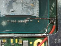
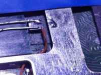
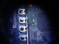
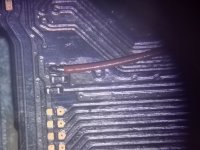
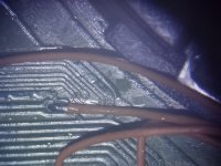
So my first attempt on a Lite bought second hand particularly to test the mod was not so great. Upon power up only got a black screen, very audible choke buzz and smoke from under the APU shield. Upon inspection the G wire got detached from the MOSFET, most likely while I was soldering it to the Pico. I used 0.2mm enamel wire for that point and in hindsight I should have secured it to something before placing the shield back, 0.2 is just to stiff for that small weld. Didn't want to commit to solder mask just yet and paid for it.
The MOSFET (single 8342) got fried obviously, but surprisingly the Switch survived. After removing the Pico and the MOSFET it power into OFW just fine. The Pico seems to be fine too, at least behaves the same upon re-flash.
Hope this experience helps someone to avoid my mistakes.
FYI, I used 0.22mm bare copper wire from 14AWG speaker wire for D and S, 30awg Kynar for 3.3V and ground and 0.1mm enamel for everything else. I'm going with 30awg on the G for the second attempt (when I find time:)).
Thank you for sharing.

From your experience, i confident that the blue screen is not because the accidentally open state of the mosfet. Just like what i predict, the mosfet will be burned, but the apu is safe, since the power is stolen by the mosfet. There is a discussion before on placing pulldown resistor between D and S so when the mosfet open, it might burn the cpu, but i am not convinced. Just for precaution, since some people reporting BSOD, which suspecting the mosfet. Now i am sure it is not the cause.
 
Last edited by abal1000x,

crazycrash_hum

Active Member
Newcomer
Joined
Nov 3, 2015
Messages
33
Trophies
0
Age
38
XP
293
Country
France
Hi everyone,
i'm wondering how to test if the Dat0 with multimeter is well posed ?
Multimeter.jpeg
This is mine

A big Thank you
 

QuiTim

Well-Known Member
Member
Joined
Mar 30, 2023
Messages
754
Trophies
0
XP
1,154
Country
Albania
So my first attempt on a Lite bought second hand particularly to test the mod was not so great. Upon power up only got a black screen, very audible choke buzz and smoke from under the APU shield. Upon inspection the G wire got detached from the MOSFET, most likely while I was soldering it to the Pico. I used 0.2mm enamel wire for that point and in hindsight I should have secured it to something before placing the shield back, 0.2 is just to stiff for that small weld. Didn't want to commit to solder mask just yet and paid for it.
The MOSFET (single 8342) got fried obviously, but surprisingly the Switch survived. After removing the Pico and the MOSFET it power into OFW just fine. The Pico seems to be fine too, at least behaves the same upon re-flash.
Hope this experience helps someone to avoid my mistakes.
FYI, I used 0.22mm bare copper wire from 14AWG speaker wire for D and S, 30awg Kynar for 3.3V and ground and 0.1mm enamel for everything else. I'm going with 30awg on the G for the second attempt (when I find time:)).
I think you experienced firsthand what happens if the G line geta disconnected. This was the reason we were discussing puttin a resistor there to avoid an issue like this.
Also i would recomand a 34-36 wire for G, it works ok.
 
  • Like
Reactions: abal1000x

abal1000x

Well-Known Member
Member
Joined
Jun 5, 2022
Messages
1,062
Trophies
0
XP
1,367
Country
Gaza Strip
Hi everyone,
i'm wondering how to test if the Dat0 with multimeter is well posed ?View attachment 374008 This is mine

A big Thank you
Multimeter.jpeg

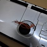
Put the switch on that red circle, then press select so theres diode symbol on the lcd. Then use the red cable to the dat0 point, and black to ground, it should be around 600. Remember DO NOT connect the battery and the usb c. The switch must be off.
 
  • Love
Reactions: crazycrash_hum

zorusgb

Well-Known Member
Newcomer
Joined
Dec 10, 2021
Messages
48
Trophies
0
Age
49
XP
142
Country
Bulgaria
I think you experienced firsthand what happens if the G line geta disconnected. This was the reason we were discussing puttin a resistor there to avoid an issue like this.
Also i would recomand a 34-36 wire for G, it works ok.
Yeah, I considered using the 0.1mm enamel for G, it's so much more forgiving, but it goes under the shield and rubbing againtst sharp edges, potentially scraping the enamel and causing a short. I recon the chances of this happening are slim, but the 30awg seems to be flexible enough. We'll see :).
Post automatically merged:

Thank you for sharing.

From your experience, i confident that the blue screen is not because the accidentally open state of the mosfet. Just like what i predict, the mosfet will be burned, but the apu is safe, since the power is stolen by the mosfet. There is a discussion before on placing pulldown resistor between D and S so when the mosfet open, it might burn the cpu, but i am not convinced. Just for precaution, since some people reporting BSOD, which suspecting the mosfet. Now i am sure it is not the cause.
I think the optional resistor is between G and S (ground essentially) and the purpose of it is to bleed out stray currents to prevent the gate from opening while the Switch is operating normally and I don't know...crashing it, burning out the APU? In this case G was disconnected so the gate would have stayed closed.
 
Last edited by zorusgb,

LogicalMadness

Well-Known Member
Member
Joined
Nov 3, 2014
Messages
287
Trophies
0
Age
41
XP
690
Country
United States
I actually don't own a switch yet, i was just wondering how easy would it be to do this, but now i am definitely gonna avoid this completely, i think xD thank you very much to both of you for helping me out tho! :)

If you truly have an interest in learning to solder, look through the tools section of the PicoFly definitive guide and get all of those. Buy an Original Xbox and learn to TSOP mod it. Then move up to a 360 SLIM RGH3 mod (fats will RROD WAY more). After those, V1\2\Lite-PFly installs should just be 'one step up'. Then the final boss that is OLED.

This goes for anyone wanting to 'learn soldering' on PFly installs. IMO
 

LuigiGad

Well-Known Member
Member
Joined
May 7, 2023
Messages
160
Trophies
0
Age
56
XP
470
Country
Italy
I would suggest you go with a bigger one (3x3mm) for starters like aon7518 or aon7506 or even bigger IRF7814 (but you have to cut the shield to fit it).
Is it a dogma to have the MOSFET inside the CPU framework? I put it together with the picofly and stretch with the point D
 

abal1000x

Well-Known Member
Member
Joined
Jun 5, 2022
Messages
1,062
Trophies
0
XP
1,367
Country
Gaza Strip
in your test did you use the single MOSFET? and this is given by the extension of point D?
Yes single mosfet, i also increase the cable diameter from 0.1mm to 0.2mm. Still failed.
I suspect the offset in the code need to be change. Right now it is 6200-6900. Since the cable is longer maybe the offset will need to compensate the delay.
 
  • Like
Reactions: QuiTim

QuiTim

Well-Known Member
Member
Joined
Mar 30, 2023
Messages
754
Trophies
0
XP
1,154
Country
Albania
Is it a dogma to have the MOSFET inside the CPU framework? I put it together with the picofly and stretch with the point D
The glitch is all about timing and the firmware from original mod of TX (same as Pico) was coded to specific timings taking in consideration mosfet parameters, switch (and modchip) operating voltages and distance/wire resistance from mosfets to apu.
There is a reason someone designed it that way because i guarantee it was easier to put the mosfets in the chip board itself.
But this is the beauty of this project, if we can come up with a way to optimise the procedure the whole comunity will benefit.
I did not try changing the location of mosfets because for me personaly it would create more problems (except if i'm to design a custom board like some users here did, then I would probably consider it because it would make more sense)
*Edit: I see @abal1000x (who else :) ) already tried it and explained why it wouldn't work. But now that we have the source code at our disposal (which I have no clue on how to read) we can make our own changes and some Switch BBQ along the way :D
 
Last edited by QuiTim,

Adran_Marit

Walküre's Hacker
OP
Member
Joined
Oct 3, 2015
Messages
3,781
Trophies
1
Location
42*South
XP
4,557
Country
Australia
If you truly have an interest in learning to solder, look through the tools section of the PicoFly definitive guide and get all of those. Buy an Original Xbox and learn to TSOP mod it. Then move up to a 360 SLIM RGH3 mod (fats will RROD WAY more). After those, V1\2\Lite-PFly installs should just be 'one step up'. Then the final boss that is OLED.

This goes for anyone wanting to 'learn soldering' on PFly installs. IMO

The number of consoles I've killed over the years while chipping is too damn high, when I first started out I killed a ps1. Since then I've killed 2 ps2 slims, succeeded several rgh3 slims, killed my lite but did an oled successfully.
 

blackheartme

Well-Known Member
Newcomer
Joined
May 28, 2021
Messages
51
Trophies
0
Age
35
XP
276
Country
Indonesia
If you truly have an interest in learning to solder, look through the tools section of the PicoFly definitive guide and get all of those. Buy an Original Xbox and learn to TSOP mod it. Then move up to a 360 SLIM RGH3 mod (fats will RROD WAY more). After those, V1\2\Lite-PFly installs should just be 'one step up'. Then the final boss that is OLED.

This goes for anyone wanting to 'learn soldering' on PFly installs. IMO
should try that boss fight in the beginning, feels like a bad ass if you wins :rofl2:
 

cgtchy0412

Well-Known Member
Member
Joined
Apr 26, 2023
Messages
287
Trophies
0
Age
41
XP
432
Country
Indonesia
Some tips, before connecting pico you need to make sure that device can boot normally with all cables dissconnected.
That would indicate good soldering at least 90 percent all the time.
Post automatically merged:

Help. long glitch. and sometimes it fails... switch lite. what should i do..? all solder in good
Check for cold join, mostly on smd resistor and enamel wire tip, also on mosfet if you use one.
 

Attachments

  • 20230527_143740.jpg
    20230527_143740.jpg
    1 MB · Views: 24
Last edited by cgtchy0412,
  • Like
Reactions: QuiTim

zorusgb

Well-Known Member
Newcomer
Joined
Dec 10, 2021
Messages
48
Trophies
0
Age
49
XP
142
Country
Bulgaria
So my first attempt on a Lite bought second hand particularly to test the mod was not so great. Upon power up only got a black screen, very audible choke buzz and smoke from under the APU shield. Upon inspection the G wire got detached from the MOSFET, most likely while I was soldering it to the Pico. I used 0.2mm enamel wire for that point and in hindsight I should have secured it to something before placing the shield back, 0.2 is just to stiff for that small weld. Didn't want to commit to solder mask just yet and paid for it.
The MOSFET (single 8342) got fried obviously, but surprisingly the Switch survived. After removing the Pico and the MOSFET it power into OFW just fine. The Pico seems to be fine too, at least behaves the same upon re-flash.
Hope this experience helps someone to avoid my mistakes.
FYI, I used 0.22mm bare copper wire from 14AWG speaker wire for D and S, 30awg Kynar for 3.3V and ground and 0.1mm enamel for everything else. I'm going with 30awg on the G for the second attempt (when I find time:)).
Well, the second attempt went better...sort off. This time no smoke, but it goes to OFW with two long and one short flashes indicating unstable glitch as per the guide (I'm on 2.73). It does glitch though when I press Reset on the joycon logo. At this point I have few options:
1. Shorten the wires. This is a must anyway as I left them ungodly long to have room to maneuver before the final assembly and lower chance to rip of the pads while initial testing.
2. Do a two MOSFET setup. I went uber conservative on the MOSFET with a single 8342 and a single cap connection. Single 8342 is fiddly enough, two would really test my skills.
3. Go for i2c as suggested in the guide.
What would you recommend to do between 2 and 3?
On one hand two MOSFET's would be a pain and the record is spotty on the success rate. On the other the i2c will mean taking off the MB (the solder points are on the back right?) and that would require removing the flex cables which I've heard horror stories about and definitely something I'm not looking forward to be fixing.
First thing first though, do a backup as Adran_Marit stressed in the other thread. I went through hell when the EMMC on my V1 bit the dust and lost everything, had no idea at the time the V1 was so easily hackable before disaster struck. I eventually managed to salvage the console with the help of the community here, but the data was gone and no online either.
BTW, any point going for 2.74 yet?
 

Attachments

  • 2016_0116_122629_001.JPG
    2016_0116_122629_001.JPG
    3.8 MB · Views: 25
  • 20230527_122245[1].jpg
    20230527_122245[1].jpg
    6.1 MB · Views: 28

cicci084

Well-Known Member
Member
Joined
Apr 1, 2023
Messages
146
Trophies
0
Age
43
XP
229
Country
Italy
Hi guys, I wanted to share this setup.
For the APU > Mosfet connections I used the self-sealing cable that I used for the PS1/PS2.
I stripped the section I needed first, then I soldered very easily as there was no need for a high temperature to melt the "lacquer/varnish" of the lacquered/varnished cable.
I photographed all the welding points so that novice users can get the clearest possible idea and can take a cue (it's not presumption, I write it because I read too often users who have problems and find broken consoles after installation ).
By the way, the last 10 consoles I've modded all worked with the single mosfet.
Both OLED, both Lite and classic switch.

Small curiosity: In this installation, on first start the rp2040 did not flash but remained fixed on the blue led for about 10 seconds and then switched to yellow. It's normal? I seem to remember that the other SWITCHES always flashed blue/cyan and then turned green (until fw 2.67) or yellow (FW2.73).

The 3/4 start, on the other hand, is lightning-fast, about 2 seconds scarce.

I post everything below.
First boot is video of 38s time.
 

Attachments

  • IMG_20230527_162715.jpg
    IMG_20230527_162715.jpg
    2.8 MB · Views: 22
  • IMG_20230527_162725.jpg
    IMG_20230527_162725.jpg
    2.2 MB · Views: 27
  • IMG_20230527_162734.jpg
    IMG_20230527_162734.jpg
    2.4 MB · Views: 19
  • IMG_20230527_181248.jpg
    IMG_20230527_181248.jpg
    1.9 MB · Views: 21
  • IMG_20230527_185922.jpg
    IMG_20230527_185922.jpg
    2.1 MB · Views: 25
  • IMG_20230527_185929.jpg
    IMG_20230527_185929.jpg
    2.2 MB · Views: 23
  • IMG_20230527_185933.jpg
    IMG_20230527_185933.jpg
    2.3 MB · Views: 20
  • IMG_20230527_190143.jpg
    IMG_20230527_190143.jpg
    2.7 MB · Views: 24
  • IMG_20230527_190212.jpg
    IMG_20230527_190212.jpg
    2.3 MB · Views: 23
  • VID_20230527_193456.mp4
    13.9 MB
  • IMG_20230527_203643.jpg
    IMG_20230527_203643.jpg
    1.7 MB · Views: 21
  • VID_20230527_235747_554.mp4
    14.3 MB
Last edited by cicci084,

QuiTim

Well-Known Member
Member
Joined
Mar 30, 2023
Messages
754
Trophies
0
XP
1,154
Country
Albania
Well, the second attempt went better...sort off. This time no smoke, but it goes to OFW with two long and one short flashes indicating unstable glitch as per the guide (I'm on 2.73). It does glitch though when I press Reset on the joycon logo. At this point I have few options:
1. Shorten the wires. This is a must anyway as I left them ungodly long to have room to maneuver before the final assembly and lower chance to rip of the pads while initial testing.
2. Do a two MOSFET setup. I went uber conservative on the MOSFET with a single 8342 and a single cap connection. Single 8342 is fiddly enough, two would really test my skills.
3. Go for i2c as suggested in the guide.
What would you recommend to do between 2 and 3?
On one hand two MOSFET's would be a pain and the record is spotty on the success rate. On the other the i2c will mean taking off the MB (the solder points are on the back right?) and that would require removing the flex cables which I've heard horror stories about and definitely something I'm not looking forward to be fixing.
First thing first though, do a backup as Adran_Marit stressed in the other thread. I went through hell when the EMMC on my V1 bit the dust and lost everything, had no idea at the time the V1 was so easily hackable before disaster struck. I eventually managed to salvage the console with the help of the community here, but the data was gone and no online either.
BTW, any point going for 2.74 yet?
I would go for short wires, single mosfet but soldered on 2 caps and fw2.74 (better glitch times)
If it works, great. If it does not, then you have eliminated all possible alternatives and you either go with i2c (i would) or "try" 2 mosfets.
Have you considered using a bigger mosfet both in capacity and/or size?
Edit: I would also add more solder to those points in pico and you should also solder to both points in the pcb for a better connection (bridge the points)
 

Site & Scene News

Popular threads in this forum

General chit-chat
Help Users
    Psionic Roshambo @ Psionic Roshambo: Hmmm it's been a long time since I messed with Retroarch on the PS3 but probably most of the...