You are using an out of date browser. It may not display this or other websites correctly.
You should upgrade or use an alternative browser.
You should upgrade or use an alternative browser.
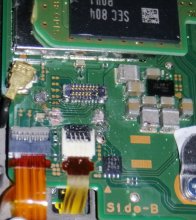
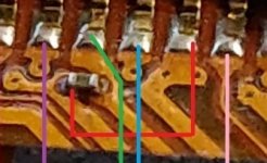
Here is Picture Ground (black) is worked when i put wire but others i don't know what's problem
Not all the pins are connected, also others that might not be bad looking might still have bad connection, I've seen this before.
I have personally sent my switch off to get a high-quality replacement done instead of bodge wires there are members of the community who can do that
Ok I will join your discord Thank you Adran_Marit :-)
Join the dragoninector one if you are going to be asking for the hardware help the others are just misc ones
https://gbatemp.net/threads/nintendo-switch-sd-card-alternative-points.579623/
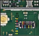
Good place to start. Your sense pin is the one that's missing. As long as the others are fine you could either solder a jumper wire from the test pad to the SD board as a quick fix or tie that point to ground to make the Switch think there's always an SD inserted. There is a good chance some other pins are damaged and just haven't detached from the connector yet though, which would require more jumper wires. Could also swap the connector itself if you have the skills and tools.
Good place to start. Your sense pin is the one that's missing. As long as the others are fine you could either solder a jumper wire from the test pad to the SD board as a quick fix or tie that point to ground to make the Switch think there's always an SD inserted. There is a good chance some other pins are damaged and just haven't detached from the connector yet though, which would require more jumper wires. Could also swap the connector itself if you have the skills and tools.
https://gbatemp.net/threads/nintendo-switch-sd-card-alternative-points.579623/
Good place to start. Your sense pin is the one that's missing. As long as the others are fine you could either solder a jumper wire from the test pad to the SD board as a quick fix or tie that point to ground to make the Switch think there's always an SD inserted. There is a good chance some other pins are damaged and just haven't detached from the connector yet though, which would require more jumper wires. Could also swap the connector itself if you have the skills and tools.
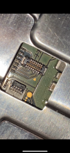
Thanks for the response, it seems like the other pins are fine, I just need to solder a wire to the SD board but, where?
Last edited by pizzaboy127,
Open the "Spoiler: Pinout SD daughter board to points on the front" spoiler in the post I linked to see what goes where.Thanks for the response, it seems like the other pins are fine, I just need to solder a wire to the SD board but, where?
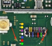
Every colour is a needed pin for the sd card to function well, the black ones and the not marked are gnd (ground) and the triangle shaped ones you marked are ground too, if you pay some closer look they are in the ground area.Hello!
Can you tell me, why some pins are not marked with a colour? Are they without a function?
And this two ground pads are not taking the solder, you know why?
Edit: So out the 16 pins of the fpc connector you only need 8 (the 7 colored and any ground you can use). So as long as any ground point is connected to the external module you should be alright.
Every colour is a needed pin for the sd card to function well, the black ones and the not marked are gnd (ground) and the triangle shaped ones you marked are ground too, if you pay some closer look they are in the ground area.
Edit: So out the 16 pins of the fpc connector you only need 8 (the 7 colored and any ground you can use). So as long as any ground point is connected to the external module you should be alright.
Hello. Thank you for the answer.
After i soldered the connector on the board, and check the contacts, all seems good. But when i plug in the sd card, i got a short circuit on the orange contact. What can be the problem, or is this normal? Only if i plug in a sd card, the contact reacts with the ground on any sd card.
And after i tried to boot, this failure on the picture cames up. Can a broken sd card slot cause this problem?
Attachments
Last edited by charliem,
From what i can tell from the picture the last testpad (from top to bottom) is hitting ground, you should clean it up before doing anything else and remember to not use mich solder, if your wire is thin you don't need much soldering. Also pleaso follow Mattyfrog pinount, because while the one from the OP is correct is not complete.
https://gbatemp.net/threads/about-the-microsd-card-connector.523130/#post-8382640
https://gbatemp.net/threads/about-the-microsd-card-connector.523130/#post-8382640
So it is normal or not, that the orange contact hits the ground after plug in a sd card?
EDIT: It works. Now it was a software problem. Maybe it was a softwareproblem from beginning?
A time ago i give the switch to a mobile shop to repair,because of a loose pin at the fpc connector on the board. i let them change the whole connector. it worked, but weeks ago it stopped working. Cant remember the failure text, but i thought it was the fpc connector for the sd card reader again. so i started soldering and learned much about this. had to happen this way.
Now i know, that i never should have change the whole fpc connector on the board, because of a loose pin, it is also possible to solder the pin back again.
But nevertheless, i would like to know, if it is normal or not, when the orange contact hits the ground after plug in a sd card.
What function is in this procedure?
Last edited by charliem,
Only if i put in the sd card. if the sd card is not in the reader, there is no reaction with the ground. And why is it still working? Have to check the sd card reader, if this is not normal.
What is the function of this contact?
Got to look over it again.
What is the function of this contact?
Got to look over it again.
Attachments
Last edited by charliem,
Only if i put in the sd card. if the sd card is not in the reader, there is no reaction with the ground. And why is it still working? Have to check the sd card reader, if this is not normal.
What is the function of this contact?
Got to look over it again.
That connect to one of the pin of the SD card flex
Similar threads
- Replies
- 3
- Views
- 966
- Replies
- 1
- Views
- 973
- Replies
- 6
- Views
- 1K
Site & Scene News
New Hot Discussed
-
-
38K views
Hackers release playable PC builds of Pokémon Legends Arceus and more following Game Freak gigaleak
We recently reported that Game Freak suffered a security breach which led to a huge amount of confidential data being leaked such as game source codes and internal... -
28K views
Homebrew Breath of the Wild demake demo found on an AliExpress DS flashcard
The Legend of Zelda: Breath of the Wild marked a huge step for the Zelda series, taking the beloved franchise and throwing it into a new and untested open world... -
27K views
Atmosphere CFW updated to pre-release v1.8.0, adds support for firmware 19.0.0
Last week, NIntendo released a major update to their Switch firmware, with the latest now being version 19.0.0. This update brought a significant amount of changes... -
23K views
Mario & Luigi: Brothership leaks online 2 weeks ahead of release
Mario & Luigi: Brothership has leaked online 2 weeks ahead of its 7th November street date. Brothership is the sixth mainline installment in the Mario & Luigi... -
18K views
Analogue will start pre-orders for their FPGA-based N64 re-imagined console "Analogue 3D"
Back in 2023, Analogue briefly teased their work on an upcoming "Analogue 3D" console, which was an FPGA-based reimaigining of the original Nintendo 64. Today, after... -
18K views
Internet Archive is now back online in a provisional read-only manner
After almost 2 full weeks since the Internet Archive suffered a security breach that caused the data of more than 31 million users to be leaked online, the Internet... -
17K views
Nintendo files lawsuit against streamer for pirating games and playing them pre-release
Nintendo's crusade against emulators continues, with a serious lawsuit being filed against a Twitch streamer who continually played and livestreamed footage of leaked... -
16K views
Nintendo Music announced, offers soundtrack collections for Nintendo Switch Online users
If you have a Nintendo Switch Online subscription, Nintendo has just released a new benefit for its users. Nintendo Music is a new mobile app that allows you to... -
15K views
"Xenoblade Chronicles X: Definitive Edition" coming to Nintendo Switch
One of the few remaining games that was still trapped on the Wii U console is now escaping its entrapment and making its way to the Nintendo Switch in 2025. Out of... -
13K views
Nintendo's Switch Online Playtest Program information has been leaked
Last week, Nintendo announced that they would be opening a registration for a beta testing for an upcoming Switch Online Playtest Program, with no details about what...
-
-
-
252 replies
Nintendo files lawsuit against streamer for pirating games and playing them pre-release
Nintendo's crusade against emulators continues, with a serious lawsuit being filed against a Twitch streamer who continually played and livestreamed footage of leaked... -
187 replies
Hackers release playable PC builds of Pokémon Legends Arceus and more following Game Freak gigaleak
We recently reported that Game Freak suffered a security breach which led to a huge amount of confidential data being leaked such as game source codes and internal... -
162 replies
Nintendo Music announced, offers soundtrack collections for Nintendo Switch Online users
If you have a Nintendo Switch Online subscription, Nintendo has just released a new benefit for its users. Nintendo Music is a new mobile app that allows you to... -
144 replies
"Xenoblade Chronicles X: Definitive Edition" coming to Nintendo Switch
One of the few remaining games that was still trapped on the Wii U console is now escaping its entrapment and making its way to the Nintendo Switch in 2025. Out of... -
132 replies
Mario & Luigi: Brothership leaks online 2 weeks ahead of release
Mario & Luigi: Brothership has leaked online 2 weeks ahead of its 7th November street date. Brothership is the sixth mainline installment in the Mario & Luigi... -
131 replies
Analogue will start pre-orders for their FPGA-based N64 re-imagined console "Analogue 3D"
Back in 2023, Analogue briefly teased their work on an upcoming "Analogue 3D" console, which was an FPGA-based reimaigining of the original Nintendo 64. Today, after... -
124 replies
Nintendo confirms that its next console will have backwards compatibility with the Switch
While leaks indicated such, and fans were hopeful, it has finally been officially confirmed: the Nintendo Switch's successor will have backwards compatibility... -
102 replies
Launch trailer for 'Dragon Age: The Veilguard' aired
Ahead of its release next week, EA and BioWare have today aired the launch trailer for Dragon Age: The Veilguard which includes a mix of cinematics and gameplay... -
95 replies
Homebrew Breath of the Wild demake demo found on an AliExpress DS flashcard
The Legend of Zelda: Breath of the Wild marked a huge step for the Zelda series, taking the beloved franchise and throwing it into a new and untested open world... -
83 replies
Thanks to homebrew creators, the Nintendo Alarmo can now run DOOM
Scene homebrew creator @GaryOderNichts is no stranger to getting custom software to run on platforms. particularly the Wii U. This time around, though, enthusiasts...
-
Popular threads in this forum
General chit-chat
-
 Xdqwerty
Loading…what are you looking at?
 -
 BigOnYa
Loading…
 -
 K3Nv2
Loading…
 -
 SpookyBaker
Loading…This is the start of a new era
-
-
-
-
-
-
-
-
-
-
-
-
-
-
-
-
-
-
-
-
-
 @
Xdqwerty:
@BigOnYa, I just wanna use this program, @deathkill781 said I could use it to edit text on nds games
@
Xdqwerty:
@BigOnYa, I just wanna use this program, @deathkill781 said I could use it to edit text on nds games -
-
-
-

