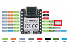
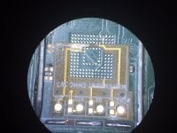
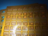
The current AIO guide has those wrong as pins 3 and 4.
You are using an out of date browser. It may not display this or other websites correctly.
You should upgrade or use an alternative browser.
You should upgrade or use an alternative browser.
Staff Posts
Recent threadmarks
sharing files
Important Posts
Recent threadmarks
FirmwaresThanks rehius, I just saw your replay from yesterday. Never would have guessed what 3 and 4 meant in the guide . There are numbers on the back of the XIAO boards next to the pins, so I just assumed the guide was wrongly pointing to overlapping pins.
What about the new 17.0.0 firmware?
I've read that switch doesn't boot with picofly. No picofly logo.
OFW seems work.
Hwfly and instinct not tested yet.
bullshit, the modchip glitches and boots to the picofly logo before any software from the switch itself is loaded.
What about the new 17.0.0 firmware?
I've read that switch doesn't boot with picofly. No picofly logo.
OFW seems work.
Hwfly and instinct not tested yet.
I have one, this oled came today deadly after update the sysnand, chip rp2040, dont work, dont charge, dont boot. Just change for instinct, and boots again into hekate, but no boot ofw, when boot emunand a message appers and say something like that [the ofw doesnt match with efuses, but will be patched and sleep mode dont work], after press button, emunand works but when you put spleep mode the switch frezze, only thing u can do is presseing about 30 seconds power button and turn on again!!!!
I have one, this oled came today deadly after update the sysnand, chip rp2040, dont work, dont charge, dont boot. Just change for instinct, and boots again into hekate, but no boot ofw, when boot emunand a message appers and say something like that [the ofw doesnt match with efuses, but will be patched and sleep mode dont work], after press button, emunand works but when you put spleep mode the switch frezze, only thing u can do is presseing about 30 seconds power button and turn on again!!!!
It seems that your modchip has burnt all your efuses...
Aww Crumbs, I did it again!
Different switch, this time. I managed to knock these off a V2 (the ones in the red box it's a picture I found online)
I didn't notice until I put it together and everything BUT the WIFI seems to be working.
Does anyone know the values? I believe they're 0201 caps.
Thanks Again,
Vic
P.s. Is there a list of trusted people who offer repairs? perhaps by location. These 0201s are at the limits of my tools/steady hands.
Attachments
u shouldve just replaced them with 100ohm that would be way easier .Sorry i just wanted to sort things out because of the desaster last time with the Board. Thank you for your help man! Next time i will use a normal Pico Zero from Waveshare.
This time i have a Nand Backup BOOT1 and BOOT2 and Keys...
I started into hekate and this time no error with EMMC. I tried launching OFW But i got Nintendo Logo then Blackscreen i forced a shut down and started it again and got Nintendo Logo (no hekate) then off again and got a Bluescreen ... I nearly got an Heart attack.... I powered it down and started it up with no SD Card and got Picofly Logo. Then i removed both Flex Cables from the Pico and powered it back on and it started up normally... Puhhhh my heart fell. I thought i messed it up again. Now im waiting for the 47Ohms resistors i bought 0603 and 0805 just in case. But im not sure how to fit them onto the chip. i can see the traces but i need to cut off the trace after the first 47ohms one and solder mine inbetween its so tiny... Do i need the second 47 ohm capacitor because of the Samsung EMMC?
View attachment 398627
View attachment 398628
My soldering doesn’t look that clean this time…
View attachment 398630
View attachment 398631
now ur gonna have to cut the traces a bit back so u can set 2 resistor behind each other.....
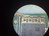
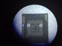
These arrived yesterday so I had time to mess around with them.
First time didn't work so I spend more than 2 hours pondered my head just to realize the balls isn't giving enough height to touch the pads due to flex but in the end it worked. I still think this was a hassle because I added small resisters to the line.
So my idea now is to move these resisters to my other flex to add more friendly sized ones and perhaps use goldfinger that latches to my other flex.
Attachments
Black Screen with sd card or No SD with card
Hello, for testing I did not replace the ram but the nvidia soc so on the faulty motherboard I put an Nvidia soc which normally works.
Result: the switch works.
Conclusion: no fault on the motherboard, however the Nvidia SOC is dead!
So for me now it's simple, a good switch (work before install Picofly) which displays a black screen with the µSD and which displays No SD without the card this means that the SOC is dead.
That sounds like a plan.
I also planned on doing that, orders the stencil but it never arrived so I don't really bother with it anymore.
So let's see if that solves the issue
Post automatically merged:
They have been tested and work.
But why use those when u can just get a tiny that fits like it is.
And be done with it
Hello, for testing I did not replace the ram but the nvidia soc so on the faulty motherboard I put an Nvidia soc which normally works.
Result: the switch works.
Conclusion: no fault on the motherboard, however the Nvidia SOC is dead!
So for me now it's simple, a good switch (work before install Picofly) which displays a black screen with the µSD and which displays No SD without the card this means that the SOC is dead.
Last edited by ppzikos,
I will rewire the Flexcable with the 0,01mm wire i bought will arrive soon hopefully. So its fine i guess i will just use the 47 ohms resistor and solder it onto the the Pads... I think this will be better. Yes i could done this but i was too stupid to realize in the moment haha Thank youu shouldve just replaced them with 100ohm that would be way easier .
now ur gonna have to cut the traces a bit back so u can set 2 resistor behind each other.....
So here is the thing XD. TLDR for people who are still new to my problem.Ok so. I checked picofly version and i was still on 2.73. I tryed several times more to update, and it finnaly worked.
After attempting to do a new NAND write from scratch with prodinfo, OFW was stuck on logo . So i did a NAND restore to my old NAND save (the one that i was getting 3539 error on ).
Now when trying to start OFW i get this screen
View attachment 398276
Well.
View attachment 398280
Knocked off RST resistor in the past,flew to narnia.Replaced with 5k resistor. Worked for a while,then i got freeze in CFW,and unable to boot OFW (stuck on logo/blackscreen after logo/2002-3539 error)+after a while was unable to glitch *=* error. Replaced the RST resistor with 4.7k as it was intended,worked for a while,then it went back to problems. Took cmd rst resistors off,resoldered them with paste and hot air, worked for a while,then problems again. Replaced emmc connector,no fix. Reballed EMMC,no fix (btw first time reballing on a "working" console, i nailed it).
Last time after a failed nand restore (stopped midway through,and gave slow emmc warning) i had NOTHING on the EMMC info window. Then the console would not even glitch *=* again. Did a reflow AGAIN on the CMD/RST resistors, now it works again :| AND I EVEN HAVE FULL INFO IN EMMC INFO . I am also able to boot into OFW. But i suspect this is not going to last long and i will have problems again. What the hell is going onnn? I tested continuity+resistance on CMD/RST and they behave like they are properly connected. I have correct resistance and continuity even after problems start to appear...
This is a picture. The white thing is solder mask. I am taking RST from emmc . I have problems with test pad RST,and emmc RST so we can rule it out. I isolated test pad rst because it was annoying to solder the wire there. Also RST resistor looks funny because i scratched the 1.8v line to have a better soldering spot when i was having trouble soldering on that place with soldering iron.
Last edited by Crung,
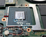
Leave clear picture for back mod reference.

where did u order the pcbs from ?Leave clear picture for back mod reference.
View attachment 398837
did u release the files for the adapter?
From jlcpcb.where did u order the pcbs from ?
did u release the files for the adapter?
https://github.com/abal1000x/emmc_adapter/releases
Using flex from @Hassal is faster, since you paste only once.
https://gbatemp.net/threads/picofly-a-hwfly-switch-modchip.622701/post-10266456
Using adapter you paste twice, first the adapter, second the emmc.
Post automatically merged:
Your conclusion is weird.Black Screen with sd card or No SD with card
Hello, for testing I did not replace the ram but the nvidia soc so on the faulty motherboard I put an Nvidia soc which normally works.
Result: the switch works.
Conclusion: no fault on the motherboard, however the Nvidia SOC is dead!
So for me now it's simple, a good switch (work before install Picofly) which displays a black screen with the µSD and which displays No SD without the card this means that the SOC is dead.
The NO SD shown means the cpu is works, since the code is RUN by the cpu to show the NO SD graphics on the lcd. If the cpu dead, no code run at all. Totally off.
Have you tried to reball the cpu, maybe theres debris, or something happened.
I think modding the cap on the cpu is risky, rather mod the cap on the back pcb. Its safer route.
Last edited by abal1000x,
I only tested with PCBWay but you have to consider they charge a minimum fee so it doesn't matter if you fabricate 5-300 units they will charge you the same sum.
Setting:
2-Layers
Thickness is minimum offered (0.1mm)
Single or Panels up to you (I chose panels with set size 13X12 they ship in default size panels)
E-Test off
Everything else should be default
There is an adhesive layer which is optional covering only the upper portion of the adapter. The purpose of this layer is to prevent it from drifting during the reflow process. It will make your life much eaiser but you can totally ignore it and use your own method to hold it in place. If you leave this intact you need to choose Tesa tape Onesided BOT.
For resister sizes it's 0402. (0603 should also fit) (Imperial size)
One thing to keep note, if your ball height isn't enough you need another scoop of paste. It threw me off the first time because I was getting a reading on my adapter but in reality some weren't even touching.
Attachments
Last edited by Hassal,
Post automatically merged:
Your conclusion is weird.
The NO SD shown means the cpu is works, since the code is RUN by the cpu to show the NO SD graphics on the lcd. If the cpu dead, no code run at all. Totally off.
Have you tried to reball the cpu, maybe theres debris, or something happened.
I think modding the cap on the cpu is risky, rather mod the cap on the back pcb. Its safer route.
i rework tegra on a good motherboard! , the result is same , no SD or black screen.
I exchanged the socs of 2 motherboards:
i have my (F) faulty switch > NOsd /black screen with sd card
and a (G) good working switch ( pico +hekate work etc...)
I put the (F) soc on the (G) motherboard and it doesn't work.
I put the (G) share on the (F) motherboard and it works!
I simply conclude : the soc is dead.
if you want to see how i work you can read this:
https://www.logic-sunrise.com/forum...error-during-lzma-decompressionswitch-hac-10/
The photos of the rework are mine but on another error on switch.
Last edited by ppzikos,
I think your methodology is flawed because its prone to error. Did you return the SoC back to the original boards?i rework tegra on a good motherboard! , the result is same , no SD or black screen.
I exchanged the socs of 2 motherboards:
i have my (F) faulty switch > NOsd /black screen with sd card
and a (G) good working switch ( pico +hekate work etc...)
I put the (F) soc on the (G) motherboard and it doesn't work.
I put the (G) share on the (F) motherboard and it works!
I simply conclude : the soc is dead.
if you want to see how i work you can read this:
https://www.logic-sunrise.com/forum...error-during-lzma-decompressionswitch-hac-10/
The photos of the rework are mine but on another error on switch.
3.3v, is that drilled? Why not just get it from the big cap near p13?Leave clear picture for back mod reference.
View attachment 398837
No its not drilled.3.3v, is that drilled? Why not just get it from the big cap near p13?
Its one of my ugly soldering
Its big pad, and i am too lazy to increase the temperature accordingly.
Last edited by abal1000x,
I think your methodology is flawed because its prone to error. Did you return the SoC back to the original boards?
This is useless ,
the motherboard which was working perfectly received the "No-sd" SOC and it does not work.
the motherboard which was not working received a "good working" SOC and it works.
this clearly indicates that:
1) SOC no-sd/blackscreen dont works on any motherboard
2) the "good working" SOC works on both motherboards.
SO:
3) the 2 motherboards are ok and capable of working with a good SOC
4) the SOC that makes no-SD / blackscreen is dead!
Similar threads
- Replies
- 3
- Views
- 1K
- Replies
- 2
- Views
- 332
- Replies
- 42
- Views
- 6K
Site & Scene News
New Hot Discussed
-
-
23K views
Wii U and 3DS online services shutting down today, but Pretendo is here to save the day
Today, April 8th, 2024, at 4PM PT, marks the day in which Nintendo permanently ends support for both the 3DS and the Wii U online services, which include co-op play...by ShadowOne333 179 -
17K views
Nintendo Switch firmware update 18.0.1 has been released
A new Nintendo Switch firmware update is here. System software version 18.0.1 has been released. This update offers the typical stability features as all other... -
16K views
The first retro emulator hits Apple's App Store, but you should probably avoid it
With Apple having recently updated their guidelines for the App Store, iOS users have been left to speculate on specific wording and whether retro emulators as we... -
16K views
Delta emulator now available on the App Store for iOS
The time has finally come, and after many, many years (if not decades) of Apple users having to side load emulator apps into their iOS devices through unofficial...by ShadowOne333 96 -
15K views
MisterFPGA has been updated to include an official release for its Nintendo 64 core
The highly popular and accurate FPGA hardware, MisterFGPA, has received today a brand new update with a long-awaited feature, or rather, a new core for hardcore...by ShadowOne333 54 -
11K views
Nintendo takes down Gmod content from Steam's Workshop
Nintendo might just as well be a law firm more than a videogame company at this point in time, since they have yet again issued their now almost trademarked usual...by ShadowOne333 113 -
10K views
TheFloW releases new PPPwn kernel exploit for PS4, works on firmware 11.00
TheFlow has done it again--a new kernel exploit has been released for PlayStation 4 consoles. This latest exploit is called PPPwn, and works on PlayStation 4 systems... -
10K views
A prototype of the original "The Legend of Zelda" for NES has been found and preserved
Another video game prototype has been found and preserved, and this time, it's none other than the game that spawned an entire franchise beloved by many, the very...by ShadowOne333 31 -
9K views
Anbernic reveals specs details of pocket-sized RG28XX retro handheld
Anbernic is back with yet another retro handheld device. The upcoming RG28XX is another console sporting the quad-core H700 chip of the company's recent RG35XX 2024... -
9K views
Nintendo "Indie World" stream announced for April 17th, 2024
Nintendo has recently announced through their social media accounts that a new Indie World stream will be airing tomorrow, scheduled for April 17th, 2024 at 7 a.m. PT...by ShadowOne333 53
-
-
-
179 replies
Wii U and 3DS online services shutting down today, but Pretendo is here to save the day
Today, April 8th, 2024, at 4PM PT, marks the day in which Nintendo permanently ends support for both the 3DS and the Wii U online services, which include co-op play...by ShadowOne333 -
113 replies
Nintendo takes down Gmod content from Steam's Workshop
Nintendo might just as well be a law firm more than a videogame company at this point in time, since they have yet again issued their now almost trademarked usual...by ShadowOne333 -
97 replies
The first retro emulator hits Apple's App Store, but you should probably avoid it
With Apple having recently updated their guidelines for the App Store, iOS users have been left to speculate on specific wording and whether retro emulators as we...by Scarlet -
96 replies
Delta emulator now available on the App Store for iOS
The time has finally come, and after many, many years (if not decades) of Apple users having to side load emulator apps into their iOS devices through unofficial...by ShadowOne333 -
79 replies
Nintendo Switch firmware update 18.0.1 has been released
A new Nintendo Switch firmware update is here. System software version 18.0.1 has been released. This update offers the typical stability features as all other...by Chary -
72 replies
TheFloW releases new PPPwn kernel exploit for PS4, works on firmware 11.00
TheFlow has done it again--a new kernel exploit has been released for PlayStation 4 consoles. This latest exploit is called PPPwn, and works on PlayStation 4 systems...by Chary -
55 replies
Nintendo Switch Online adds two more Nintendo 64 titles to its classic library
Two classic titles join the Nintendo Switch Online Expansion Pack game lineup. Available starting April 24th will be the motorcycle racing game Extreme G and another...by Chary -
54 replies
MisterFPGA has been updated to include an official release for its Nintendo 64 core
The highly popular and accurate FPGA hardware, MisterFGPA, has received today a brand new update with a long-awaited feature, or rather, a new core for hardcore...by ShadowOne333 -
53 replies
Nintendo "Indie World" stream announced for April 17th, 2024
Nintendo has recently announced through their social media accounts that a new Indie World stream will be airing tomorrow, scheduled for April 17th, 2024 at 7 a.m. PT...by ShadowOne333 -
52 replies
The FCC has voted to restore net neutrality, reversing ruling from 2017
In 2017, the United States Federal Communications Commission (FCC) repealed net neutrality. At the time, it was a major controversy between internet service providers...by Chary
-
Popular threads in this forum
General chit-chat
- No one is chatting at the moment.
-
 @
BigOnYa:
@SylverReZ I've never used a disposable, seems like a waste. kinda cool idea tho. It would be nice to have vape built in to a cell phone even. "The iVape"+1
@
BigOnYa:
@SylverReZ I've never used a disposable, seems like a waste. kinda cool idea tho. It would be nice to have vape built in to a cell phone even. "The iVape"+1 -
-
-
-
-
-
 @
K3Nv2:
I was hoping I could add a custom ROM to this fire HD 10 tablet but guess no one's made twrp available
 -
-
-
-
-
-
-
-
-
-
-
-
-
-
 @
ZeroT21:
only ps5 updated to latest firmware can go on psn, jailbroken ones just don't use psn or they risk getting flagged or banned, altho spouting profanity in online play alredy does that
 -
-
-
Y @ YuseiFD:Then how come you do it and don't get banned ? or is it a question of getting caught doing it ?
-

