Hacking Hardware Picofly - a HWFLY switch modchip

morganno

Active Member
Newcomer
Joined
Aug 7, 2018
Messages
27
Trophies
0
Age
48
XP
307
Country
France
I wonder what is the science behind these phenomenon.
Its taking the conscious mind to choose the 4th pin than the 3rd pin.
Even i didn't realize at first, until someone point it out.
My mind also choose the 4th pin. :rofl2 :
but the worst part is that I have the diagrams in front of my eyes😵‍💫😵‍💫🧐 and it's not my first console. something crazy🤪🤪🤪
 
  • Haha
Reactions: abal1000x

QuiTim

Well-Known Member
Member
Joined
Mar 30, 2023
Messages
758
Trophies
0
XP
1,189
Country
Albania
I wonder what is the science behind these phenomenon.
Its taking the conscious mind to choose the 4th pin than the 3rd pin.
Even i didn't realize at first, until someone point it out.
My mind also choose the 4th pin. :rofl2:
same here, if I just try to do it blindly (by intuition) I would chose the 4th pin.
It's like the default setting in the brain is 4th pin....interesting indeed.
Post automatically merged:

but the worst part is that I have the diagrams in front of my eyes😵‍💫😵‍💫🧐 and it's not my first console. something crazy🤪🤪🤪
Did you take CLK from the emmc as well? Did it work?
 
  • Haha
Reactions: abal1000x

Doulos

Member
Newcomer
Joined
Aug 29, 2023
Messages
6
Trophies
0
Age
99
XP
41
Country
United States
Howdy y'all.
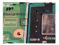
I seem to have broke something when installing my picofly on my V1 switch. It happened when taking off the heat cover.

Sorry, I know it's not the best picture. I took this before I tried re-attaching it. - I ended up losing it after multiple failed attempts to re-attach.

What is the part & Does anyone have any suggestions on how to re-attach it? It's so small it kept wanting to stick to the iron when I lifted it.

Thanks

broken.jpg
 

QuiTim

Well-Known Member
Member
Joined
Mar 30, 2023
Messages
758
Trophies
0
XP
1,189
Country
Albania
Howdy y'all.
I seem to have broke something when installing my picofly on my V1 switch. It happened when taking off the heat cover.

Sorry, I know it's not the best picture. I took this before I tried re-attaching it. - I ended up losing it after multiple failed attempts to re-attach.

What is the part & Does anyone have any suggestions on how to re-attach it? It's so small it kept wanting to stick to the iron when I lifted it.

Thanks

View attachment 391211
Those are used for Wifi/BT I think.
You need a fine tip iron (0.1mm) and some fine tweezers to work with components that size.
Remove the cap, clean the area with flux and wick, add some fresh solder to the pads (preferably low melt) then hold the new capacitors in place and solder them in place with iron.
You can also use solder paste and hot air station but I will assume you don't have those.
Good luck
P.S. and are you sure you should be doing this kind of work at 98yrs old :D
 

Attachments

  • temp1.png
    temp1.png
    1.1 MB · Views: 26

Doulos

Member
Newcomer
Joined
Aug 29, 2023
Messages
6
Trophies
0
Age
99
XP
41
Country
United States
Those are used for Wifi/BT I think.
You need a fine tip iron (0.1mm) and some fine tweezers to work with components that size.
Remove the cap, clean the area with flux and wick, add some fresh solder to the pads (preferably low melt) then hold the new capacitors in place and solder them in place with iron.
You can also use solder paste and hot air station but I will assume you don't have those.
Good luck
P.S. and are you sure you should be doing this kind of work at 98yrs old :D
lol, I hit the wrong year & can't change it. Thanks. I need to figure out what the part is so I can get another.
 

lightninjay

Well-Known Member
Member
Joined
Mar 28, 2023
Messages
561
Trophies
0
Age
31
XP
1,400
Country
United States
lol, I hit the wrong year & can't change it. Thanks. I need to figure out what the part is so I can get another.
As QuiTim has pointed out, it's in the image he provided. If you are unsure on a source for them, the guide can direct you to some that are removable from rp2040-Zero's and rp2040-One's
 
  • Like
Reactions: QuiTim

Doulos

Member
Newcomer
Joined
Aug 29, 2023
Messages
6
Trophies
0
Age
99
XP
41
Country
United States
Sorry I didn't see the picture in the response. Thanks for all the help. I've got some fine tips for my iron on the way, I'll wait until they get here before I try anything..
 
  • Like
Reactions: QuiTim

karatefeet

Well-Known Member
Newcomer
Joined
May 18, 2023
Messages
90
Trophies
0
XP
494
Country
Canada
Having an issue flashing the latest batch of RP Tiny that I just got. Have tried 3 out of the 5 and none are flashing. Both my programmer and chip are v1.1. Doing the same procedure as the previous ones I've flashed - hold boot, connect the usb. I get a red light on the programmer which I can't remember if it's normal. Drag the fw file over and nothing, led on the Tiny doesn't do anything. I tried connecting 5v / 3.3v and ground to the Tiny and the led doesn't light up.

Anyone having this problem? All my RP2040 chips (zero and tiny) have been from this same seller with zero issues so I'm very confused.
 
Last edited by karatefeet,
  • Like
Reactions: Danook28

abal1000x

Well-Known Member
Member
Joined
Jun 5, 2022
Messages
1,070
Trophies
0
XP
1,419
Country
Gaza Strip
Having an issue flashing the latest batch of RP Tiny that I just got. Have tried 3 out of the 5 and none are flashing. Both my programmer and chip are v1.1. Doing the same procedure as the previous ones I've flashed - hold boot, connect the usb. I get a red light on the programmer which I can't remember if it's normal. Drag the fw file over and nothing, led on the Tiny doesn't do anything. I tried connecting 5v / 3.3v and ground to the Tiny and the led doesn't light up. I'm confused.

Anyone having this problem?
Try to use another usb port, a usb2 port is safer.
 

karatefeet

Well-Known Member
Newcomer
Joined
May 18, 2023
Messages
90
Trophies
0
XP
494
Country
Canada
Try to use another usb port, a usb2 port is safer.


Ok I tried a usb2 port and still not flashing. The new batch has a bigger connector compared to the first ones I used.
Wonder if something changed. Tried all 5 and none flash. I did see a reviewer saying they got some that won't flash. Guess I'll contact the seller.
 

Attachments

  • IMG_0773.jpg
    IMG_0773.jpg
    2.1 MB · Views: 29
  • IMG_0692.jpg
    IMG_0692.jpg
    3.1 MB · Views: 20

Dee87

Well-Known Member
Member
Joined
Mar 19, 2023
Messages
1,139
Trophies
1
XP
1,590
Country
Germany
Ok I tried a usb2 port and still not flashing. The new batch has a bigger connector compared to the first ones I used.
Wonder if something changed. Tried all 5 and none flash. I did see a reviewer saying they got some that won't flash. Guess I'll contact the seller.
Original or clone?
 

Byomi

Member
Newcomer
Joined
Jul 2, 2023
Messages
5
Trophies
0
Age
39
XP
35
Country
Austria
Hi everyone. Just found a recent video of rp2040 tiny installation into a splatoon OLED. I got a ZELDA Oled and want to do the same BUT use the MOSFET on backside solution from abal1000x. There's also no DAT0-adapter used in the video linked. Would you recommend to do it like that and do you expect any differences between a Splatoon and Zelda Oled? And which MOSFET do I need to buy?

 
  • Like
Reactions: Danook28

Dee87

Well-Known Member
Member
Joined
Mar 19, 2023
Messages
1,139
Trophies
1
XP
1,590
Country
Germany
Hi everyone. Just found a recent video of rp2040 tiny installation into a splatoon OLED. I got a ZELDA Oled and want to do the same BUT use the MOSFET on backside solution from abal1000x. There's also no DAT0-adapter used in the video linked. Would you recommend to do it like that and do you expect any differences between a Splatoon and Zelda Oled?


there is no really hardware difference between the splatoon and zelda edition , maybe just a different emmc brand but everything else is the same.

there is a dat0 adapter used in that video....

i dont use dat0 adapter but if u dont have any experience in using a hotair station i wouldnt recommend it.

also if u dont have any experience in soldering i would also recommend let someone do it who knows what hes doing.
if u dont have experience it is doable but u need to be carefull and have the correct equipment.

u can do the mosfet on the backside , i had some devices not glitch fast enough with back side mosfets so im still installing them on the apu like normaly.

so that up to u and how the device works with the backside mosfet.
 
  • Like
Reactions: Danook28

Byomi

Member
Newcomer
Joined
Jul 2, 2023
Messages
5
Trophies
0
Age
39
XP
35
Country
Austria
Hi and thanks for your reply. I have an electrician who already did me some electrical mods like the foolography Nikon TC-16A mod. He has already repaired dozens of phones so I think he is the right one to do the job. Just need to provide him with the correct parts. I already know that i need rev1.1 of rp2040 tiny and for the rest I am still unsure.
 

QuiTim

Well-Known Member
Member
Joined
Mar 30, 2023
Messages
758
Trophies
0
XP
1,189
Country
Albania
Waveshare ones work great
Post automatically merged:


would 6.3V also work?
Well that rail is 3.3v or maybe 5v (not sure, did not measure) but a 6.3v cap should be enough.
Post automatically merged:

Hi and thanks for your reply. I have an electrician who already did me some electrical mods like the foolography Nikon TC-16A mod. He has already repaired dozens of phones so I think he is the right one to do the job. Just need to provide him with the correct parts. I already know that i need rev1.1 of rp2040 tiny and for the rest I am still unsure.
Also, keep in mind that you might need to add another resistor on dat0 on rp-tiny if it does not work, so if your guy is up to the task you might as well ask him to replace the 2 x 47ohm resistors (dat0 and cmd) with 100ohm ones (so you don't have any issue afterwards.
 

Site & Scene News

Popular threads in this forum

General chit-chat
Help Users
  • No one is chatting at the moment.
    HiradeGirl @ HiradeGirl: What.