Hacking Hardware Picofly - a HWFLY switch modchip

abal1000x

Well-Known Member
Member
Joined
Jun 5, 2022
Messages
1,070
Trophies
0
XP
1,405
Country
Gaza Strip
So I did some research. These resistors on an OLED CMD should show 4.7k and 47 ohms right? Mine showed no value when tested and in diode they show 350 one way, 750 the other. This means they've blown? (I have a black screen when booting).

If so what size are the resistors so I can order new ones and can a faulty CPU flex cable install cause them to blow? I still need to work out what happened.
https://gbatemp.net/threads/picofly-a-hwfly-switch-modchip.622701/post-10171602

4.7K and 47K

" Mine showed no value when tested"
If what you mean is
you test the resistance value and it is not measured,
than surely its damaged, need to replace.
 
Last edited by abal1000x,
  • Like
Reactions: Uberfish

QuiTim

Well-Known Member
Member
Joined
Mar 30, 2023
Messages
757
Trophies
0
XP
1,178
Country
Albania
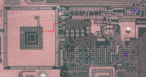
Well, this is my preliminary investigation results: a dat0 ripoff. @abal1000x @QuiTim
@Dee87

View attachment 377775

View attachment 377777

Well, my switch lite worked for four days after a "successful" pico install, full hekate's nand backup and etc.

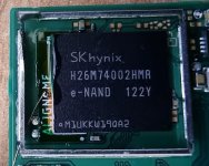
In two different episodes I was some OS freezing... In the last freeze, I forced a power off, and since, black screen and the Led code was "*=* No eMMC block 0 read error" I checked that the wires had continuity, there was no grounding. So I removed the chip, the wires and now under the microscope I noticed that my dat0 was ripped out. I don't know if this happened during chip removal, after the black screen or if it was already like that. Could this be related to my black screen?

Thx for the help.
Well, this is good news, in a way :)
I would try a couple of things here to fix that trace.
1. Easy - Cover the surrounding points with kapton/solder mask and put a blob of solder there in hope that it will create a short between the 2 points (use good flux and sn/pb solder)
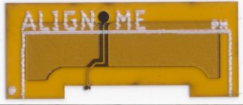
2. Medium - use this specific dat0 adapter (as in Oled) as it has no anchor points and then create a bridge from dat0 to one of the points where it need to be (check picture "a5" the blue X on top right)
3. Hard - use a 0.02 jump wire to try to fix the broken trace between two points.
Picture legend:
a1=dat0 in place in oled to give you an idea of size;
a2=dat0 that im talking about;
a3=how it should be placed;
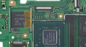
a4=whats going on beneath;
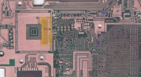
a5=Lite board traces
This is pretty much what @abal1000x is saying but with pictures :D
 

Attachments

  • a1.JPG
    a1.JPG
    71.2 KB · Views: 30
  • a2.JPG
    a2.JPG
    35.9 KB · Views: 36
  • a3.JPG
    a3.JPG
    258.2 KB · Views: 31
  • a4.JPG
    a4.JPG
    434.3 KB · Views: 31
  • a5.JPG
    a5.JPG
    431.8 KB · Views: 36

Uberfish

Active Member
Newcomer
Joined
Jan 5, 2014
Messages
44
Trophies
0
Location
Tangerang
XP
101
Country
Indonesia
https://gbatemp.net/threads/picofly-a-hwfly-switch-modchip.622701/post-10171602

4.7K and 47K

" Mine showed no value when tested"
If what you mean is
you test the resistance value and it is not measured,
than surely its damaged, need to replace.
Yep! Theres no value when measured. I tested diode to check it just wasn't a bad multimeter probe contact and there's a voltage drop. Does anyone have the size of these resistors?

Out of interest, since I'm not experienced with smd testing, why is there no resistance value but still a voltage drop? I guess it's because the resistors are connected to the board and I'm measuring the drop across ground to the other component?
 

floxcap

Well-Known Member
Newcomer
Joined
May 21, 2023
Messages
69
Trophies
0
XP
281
Country
Australia
DragonFly

Just got my dragonFly boards in, I'll let you guys know how they go :shit:
Also I made some changes and have ordered some to be assembled. If everything goes well you guys can have some to test.
  • Dual MOSFET onboard in single package
  • CMOS oscillator
  • All components are virtually the smallest available package size
  • Ideally would be made of 0.1mm flex, but 0.8mm/1mm FR4 is cheap and good enough for this revision
  • 22mmx13mm(7/8"x1/2"), final version will be 15mmx10mm(5/8"x3/8")
  • I think I'll sell them for $15 AUD ($10 USD)
  • Most importantly, rounded traces :)
View attachment 377641View attachment 377639

Nice job. Do you think there are any risks with putting the mosfet(s) on-board?
Personally I'd be concerned with current/ground/capacitance issues - I think it's better to have the mosfets as close as possible to the CPU to mitigate these problems.
It'll be interesting to see how you go with these - especially over the longer term - good luck :)
 
  • Like
Reactions: CodyRoseman

CodyRoseman

Active Member
Newcomer
Joined
Apr 27, 2023
Messages
41
Trophies
0
Age
27
XP
101
Country
Australia
Nice job. Do you think there are any risks with putting the mosfet(s) on-board?
Personally I'd be concerned with current/ground/capacitance issues - I think it's better to have the mosfets as close as possible to the CPU to mitigate these problems.
It'll be interesting to see how you go with these - especially over the longer term - good luck :)
Only one way to find out. I think it should be ok. the apu only ever sees 2amps during full load, and that current isnt going near that capacitor and especially not 2amps during boot.
 

floxcap

Well-Known Member
Newcomer
Joined
May 21, 2023
Messages
69
Trophies
0
XP
281
Country
Australia
Well, this is good news, in a way :)
I would try a couple of things here to fix that trace.
1. Easy - Cover the surrounding points with kapton/solder mask and put a blob of solder there in hope that it will create a short between the 2 points (use good flux and sn/pb solder)
2. Medium - use this specific dat0 adapter (as in Oled) as it has no anchor points and then create a bridge from dat0 to one of the points where it need to be (check picture "a5" the blue X on top right)
3. Hard - use a 0.02 jump wire to try to fix the broken trace between two points.
Picture legend:
a1=dat0 in place in oled to give you an idea of size;
a2=dat0 that im talking about;
a3=how it should be placed;
a4=whats going on beneath;
a5=Lite board traces
This is pretty much what @abal1000x is saying but with pictures :D
Point #3 - Haha - yep - I ended up with ripped pads when trying to figure out why my first lite install didn't work (solder, remove, re-solder etc)... except in my case it was both pads - so I had to dig down a layer to get to the copper below for both pads and re-join them :unsure:
It worked - but not at fun thing to have to do.
 

CodyRoseman

Active Member
Newcomer
Joined
Apr 27, 2023
Messages
41
Trophies
0
Age
27
XP
101
Country
Australia
Nice job. Do you think there are any risks with putting the mosfet(s) on-board?
Personally I'd be concerned with current/ground/capacitance issues - I think it's better to have the mosfets as close as possible to the CPU to mitigate these problems.
It'll be interesting to see how you go with these - especially over the longer term - good luck :)
the parasitic capacitance from the ground planes should be completely negligable for this application, but the resistance and current capabilities of the trace width might. Ill find out
 

Switxh

Well-Known Member
Member
Joined
Mar 11, 2023
Messages
110
Trophies
0
Age
28
XP
273
Country
United Kingdom
I've got a Lite doing the same and it doesn't seem like *you've gotten an answer, correct?
Yeah unfortunately I never found the cause or a solution to the problem. Every other Switch I have done had a Samsung EMMC. That OLED with the slow / random glitch times was the only SK Hynix I have done. I am inclined to put it down to the SK Hynix chip just sucking. Every other Picofly install I have done the glitch times are almost instant. 1-2 seconds at most.
 

QuiTim

Well-Known Member
Member
Joined
Mar 30, 2023
Messages
757
Trophies
0
XP
1,178
Country
Albania
On the pic, a3 is a Switch Lite model, that i know, no need a DAT0 adaptator on switch lite...
you are right but we have a specific situation here. the dat0 on pcb has been damaged and we are going through ideas on how to fix it. read the posts above that one and you'll get the full picture
 

abal1000x

Well-Known Member
Member
Joined
Jun 5, 2022
Messages
1,070
Trophies
0
XP
1,405
Country
Gaza Strip
Both, actually 🤦‍♂️ I initially thought I maybe overheated them during the soldering but I only tapped with the iron, not held it there. So I'm wondering what could cause them to blow...
When you asked why that could happened.

I assume your soldering is okay, no short circuit, then one possible scenario is...
You inserted a conducting debris to the emmc when inserting the adapter. The right resistor is connected to the Data Strobe pin of the emmc, which near the vss
a.png
 

Switxh

Well-Known Member
Member
Joined
Mar 11, 2023
Messages
110
Trophies
0
Age
28
XP
273
Country
United Kingdom
I've not had any issues, I'm not sure what all the fuss is about. I get 400-690 on diode tests no problem?
The diode reading on DAT1 and DAT0 is the same. Even if you bridge them you will still get the same diode reading. Bridging DAT1 and DAT0 is no joke and will cause corruption.
 

RiotRetroGaming

Well-Known Member
Newcomer
Joined
Mar 25, 2023
Messages
60
Trophies
0
Age
43
XP
164
Country
United Kingdom
The diode reading on DAT1 and DAT0 is the same. Even if you bridge them you will still get the same diode reading. Bridging DAT1 and DAT0 is no joke and will cause corruption.

Ah ok, that gives a bit more clarity 👍
Post automatically merged:

Ah ok, that gives a bit more clarity 👍

I've just been given this to do... this should be fun! 😅
 

Attachments

  • received_633150075503930.jpeg
    received_633150075503930.jpeg
    137.2 KB · Views: 31

cicci084

Well-Known Member
Member
Joined
Apr 1, 2023
Messages
146
Trophies
0
Age
44
XP
239
Country
Italy
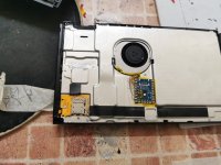
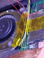
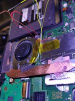
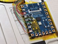
1) Hi guys, today they deliver this console to me, I will update you on the solution.

2) In the meantime, I have a solution with this console which side are the EMUMMC? (click for help me, more info)

3). I also installed a multicolor picofly (cables), in my opinion the cabling (especially CPU) lengthens unnecessarily.
 

Attachments

  • WhatsApp Image 2023-06-14 at 12.45.05.jpeg
    WhatsApp Image 2023-06-14 at 12.45.05.jpeg
    294.2 KB · Views: 37
  • WhatsApp Image 2023-06-14 at 12.45.25 (1).jpeg
    WhatsApp Image 2023-06-14 at 12.45.25 (1).jpeg
    236.3 KB · Views: 31
  • WhatsApp Image 2023-06-14 at 12.45.25 (2).jpeg
    WhatsApp Image 2023-06-14 at 12.45.25 (2).jpeg
    475.7 KB · Views: 28
  • WhatsApp Image 2023-06-14 at 12.45.25 (3).jpeg
    WhatsApp Image 2023-06-14 at 12.45.25 (3).jpeg
    276.6 KB · Views: 33
  • WhatsApp Image 2023-06-14 at 12.45.25 (4).jpeg
    WhatsApp Image 2023-06-14 at 12.45.25 (4).jpeg
    285.4 KB · Views: 28
  • WhatsApp Image 2023-06-14 at 12.45.25.jpeg
    WhatsApp Image 2023-06-14 at 12.45.25.jpeg
    216.6 KB · Views: 38
  • Like
Reactions: abal1000x

Uberfish

Active Member
Newcomer
Joined
Jan 5, 2014
Messages
44
Trophies
0
Location
Tangerang
XP
101
Country
Indonesia
When you asked why that could happened.

I assume your soldering is okay, no short circuit, then one possible scenario is...
You inserted a conducting debris to the emmc when inserting the adapter. The right resistor is connected to the Data Strobe pin of the emmc, which near the vss
View attachment 377828
I'd be super surprised if any debris got that far under the emmc, I'm not using any sprays or inserting the adaptor with force. I haven't inspected the CPU flex cable yet, it was suggested that could cause issues if there's a short somewhere around that. After I installed it I did continuity testing, and it passed. Any idea on that?
 
  • Like
Reactions: abal1000x

Site & Scene News

Popular threads in this forum

General chit-chat
Help Users
  • No one is chatting at the moment.
    K3Nv2 @ K3Nv2: https://youtube.com/shorts/FdYTKAVSsXY?si=9E-2AU0JN-4hRZi3