Hacking Hardware Picofly - a HWFLY switch modchip

lightninjay

Well-Known Member
Member
Joined
Mar 28, 2023
Messages
560
Trophies
0
Age
31
XP
1,375
Country
United States
so you recomend to stick to the rp2040zero , im worry about having to cut the metal shield of the console on v2 mariko , i dont like that
I am not saying that the tiny won't work, but if you haven't been following along on the thread, then you won't know that the tiny has three incorrect resistors added that need to be removed/replaced before installation. That could be dangerous for your Switch.

The 2040-Zero is at least proven so far.
 
  • Like
Reactions: 1337_Ninja

Takezo-San

Well-Known Member
Member
Joined
May 3, 2023
Messages
261
Trophies
0
Age
39
XP
349
Country
Seychelles
so you recomend to stick to the rp2040zero , im worry about having to cut the metal shield of the console on v2 mariko , i dont like that
I have cut the shield on a v1 and v2, no problems at all. As long as you have Kapton tape to tape the cut edges if you want be safer from potential shorts.
 

Cristiano04

Member
Newcomer
Joined
Oct 27, 2021
Messages
19
Trophies
0
Age
37
XP
605
Country
Brazil
hello everyone, I did the whole process of installing the emunand chip, but when starting the environment I get this error, does anyone know a way to solve this?
 

Attachments

  • db2b60cd-8deb-4d29-8725-779f82440845.jpeg
    db2b60cd-8deb-4d29-8725-779f82440845.jpeg
    125.3 KB · Views: 42

btjunkster

Member
Newcomer
Joined
May 15, 2023
Messages
6
Trophies
0
Age
44
XP
75
Country
United States
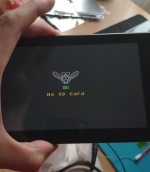
Hi all. I have an animal crossing v2. Installed Picoboot but kept getting blue light then yellow light and nothing happens. I have to then hold power button for 10 seconds or so before the console will allow me to reboot again.

I have double checked the Dat0 connection and it seems fine.

When I removed Picofly. The console is able to boot normally.

Appreciate any pointer at all. I read somewhere EMMC could be incompatible. How do I check that?
 

abal1000x

Well-Known Member
Member
Joined
Jun 5, 2022
Messages
1,063
Trophies
0
XP
1,371
Country
Gaza Strip
Hi all. I have an animal crossing v2. Installed Picoboot but kept getting blue light then yellow light and nothing happens. I have to then hold power button for 10 seconds or so before the console will allow me to reboot again.

I have double checked the Dat0 connection and it seems fine.

When I removed Picofly. The console is able to boot normally.

Appreciate any pointer at all. I read somewhere EMMC could be incompatible. How do I check that?
Its really yellow, right (no kapton tape upon it).

If it is, you might check the D0, CMD, and CLK line.
These three minimum requirement to do R/W to the emmc.
 

Takezo-San

Well-Known Member
Member
Joined
May 3, 2023
Messages
261
Trophies
0
Age
39
XP
349
Country
Seychelles
Hi all. I have an animal crossing v2. Installed Picoboot but kept getting blue light then yellow light and nothing happens. I have to then hold power button for 10 seconds or so before the console will allow me to reboot again.

I have double checked the Dat0 connection and it seems fine.

When I removed Picofly. The console is able to boot normally.

Appreciate any pointer at all. I read somewhere EMMC could be incompatible. How do I check that?
Use multimeter to check for shorts
 

AceCuba

Well-Known Member
Newcomer
Joined
Feb 4, 2021
Messages
79
Trophies
0
Age
25
Location
Mi cueva
XP
300
Country
Cuba
I am not saying that the tiny won't work, but if you haven't been following along on the thread, then you won't know that the tiny has three incorrect resistors added that need to be removed/replaced before installation. That could be dangerous for your Switch.

The 2040-Zero is at least proven so far.
Can you tell my what are the resistors and what values need to be the new ones . Im folloing the thread but its long as hell jajaj

Enviado desde mi Redmi Note 8 mediante Tapatalk
 

DesDeux

Member
Newcomer
Joined
May 11, 2023
Messages
22
Trophies
0
Age
30
XP
67
Country
Belgium
There is a hole in kapton, but light is definitely cyan as it's not working, I tried to add 20k resistor on rst and nothing changed, except ofw stops working(without resistor it's loads fine). Well, then will try to solder two mosfets, as i resolder one around 3 or 4 times already with same result.
Finally, two mosfets actually helped and now it's working. Well, almost, now need to setup cfw to be sure i'm not having slow emmc errors or other similar shit.
 

Attachments

  • finally.png
    finally.png
    370.8 KB · Views: 40

QuiTim

Well-Known Member
Member
Joined
Mar 30, 2023
Messages
756
Trophies
0
XP
1,159
Country
Albania
Last edited by QuiTim,

DesDeux

Member
Newcomer
Joined
May 11, 2023
Messages
22
Trophies
0
Age
30
XP
67
Country
Belgium
Finally, two mosfets actually helped and now it's working. Well, almost, now need to setup cfw to be sure i'm not having slow emmc errors or other similar shit.
Also, is 32gb microsd enough for testing things like installing atmosphere, making backups and etc (simply don't have bigger sd at the moment)?
 

btjunkster

Member
Newcomer
Joined
May 15, 2023
Messages
6
Trophies
0
Age
44
XP
75
Country
United States
Its really yellow, right (no kapton tape upon it).

If it is, you might check the D0, CMD, and CLK line.
These three minimum requirement to do R/W to the emmc.
Hi bro. I took a break and came back for a second attempt. Took out all the wires for D0, CMD and CLk and it boot up into Hekate first try. I was getting worried that there is something wrong with this EMMC.

Thanks a bunch!
 

Warbeast

Active Member
Newcomer
Joined
Dec 30, 2015
Messages
40
Trophies
0
Age
44
XP
294
Country
Anyone knew what issue will be if the caps on red is not installed, as i missing it when cleaning the point.
Install is success and in fact now my kids playing on it. Only issue is touch screen is not working, it was working before of course. Any clue?
Thats pin six of m92t36 which is vsvr 3.3v the cap is a decoupling cap 1uf or 2.2uf it wouldn't stop the touch screen working Pin five next to it is vccin 3.3v I believe pin 5 and 6 are to do with voltage from battery or mainboard
Post automatically merged:

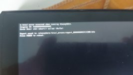
hello all, do you know what is the problem with this swich v2? it cannot boot cfw and ofw and shown as the picture below.
thanks.
View attachment 371486
That error code Ive had with a batch of fake m92t36 chips from aliexpress.
As you soldered the 3.3v and ground to it I'm guessing it must be a fault with the chip or the soldering around it check for shorts around it
 
Last edited by Warbeast,
  • Like
Reactions: QuiTim

Jorian

Member
Newcomer
Joined
May 15, 2023
Messages
16
Trophies
0
Age
36
XP
43
Country
France
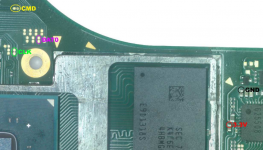
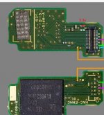
Hi everyone, thanks you for all the good information here, I have one question, someone know if we have an alternativ 3.3v on the switch V2 mariko ? it my last point to solder and it's really tricky for me, I almost destroy the point, but the switch still work fine. I just look for one different way to get the 3.3v on my picofly...if someone can help me !

Thank you so much...
 

Attachments

  • Capture d’écran 2023-05-15 195329.png
    Capture d’écran 2023-05-15 195329.png
    670.3 KB · Views: 38

QuiTim

Well-Known Member
Member
Joined
Mar 30, 2023
Messages
756
Trophies
0
XP
1,159
Country
Albania
Hi everyone, thanks you for all the good information here, I have one question, someone know if we have an alternativ 3.3v on the switch V2 mariko ? it my last point to solder and it's really tricky for me, I almost destroy the point, but the switch still work fine. I just look for one different way to get the 3.3v on my picofly...if someone can help me !

Thank you so much...
Use this one on emmc board.
 

Attachments

  • Screenshot_20230319_134832_Gallery.jpg
    Screenshot_20230319_134832_Gallery.jpg
    154.8 KB · Views: 58

bilalhassan341

Well-Known Member
Member
Joined
Apr 1, 2023
Messages
138
Trophies
0
XP
271
Country
United States
lite and v1 is well documented.
https://balika011.hu/switch/

oled and v2, waiting for some good guys to salvage their NS pcbs , sandpaper it, layer by layer, and upload it to the internet.
Post automatically merged:


Green means the glitch is confirmed.
Try to check the RST line.

From rehius:
Q: GREEN, but instant reset
A: Clean flux near the RST point
I Cleaned the RST point and also tried to solder to diff RST point and cleaned it also with alchol confirm point is cleaned no flux but still same issue.
 

Site & Scene News

Popular threads in this forum

General chit-chat
Help Users
    Psionic Roshambo @ Psionic Roshambo: https://www.youtube.com/watch?v=-Eo3Bh06drc