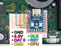
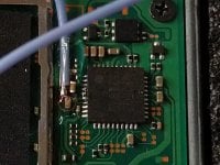
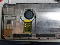
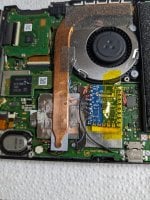
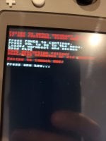
Anyone know an alternate RST point on an Erista? Not on the EMMC board, but somewhere else? The RST point on my EMMC came off.
You are using an out of date browser. It may not display this or other websites correctly.
You should upgrade or use an alternative browser.
You should upgrade or use an alternative browser.
Staff Posts
Recent threadmarks
sharing files
Important Posts
Recent threadmarks
FirmwaresThanks I found the point, as far as I can tell, the little black component on your photo isn't on my board though. Is that any issue?View attachment 363113
The blue line leads to a tiny pad near the EMMC, but not on it, so you should be able to hit that one.
edit: tried it, still won't show me the chip's boot screen again. Possibly I have another wire that's an issue though. It's just booting straight into OFW.
edit: I'm getting yellow LED and then it goes to OFW. I checked my D0 point it is good on both ends. Not sure what's going on.
edit: RST came off, so.. it's real difficult to hit that point its very small. so I think I'll shelve this til tomorrow. Since I have SP1 and SP2 perfectly soldered, I might just buy a different modchip altogether because this one pretty much gave up on me hehe
Last edited by realtimesave,
Thanks for this my picofly on switch lite works..with fw2.5+unlock my issue is when I power on my switch the light is cyan and boot to ofw..but when I press the reset when switch logo it glitch to green light and boot to hekate.but when I flash this 2.6 it glitch to green no more click in reset and succesfully boot to hekate.i use 2 mosfet.by the way my RP2040 is like this and the version I see inside when I flash is v3.0. so 2.6 is the firmware compatible.the 2.5 seems have a bug to this R2040 v3.0NOT tested, so NOT putting into the main post (will be updated once I test everything).
no guarantees, use at your own risk.
for those who can't wait
!!!!PINOUT!!!! (resistors / mosfets are still required)
Common GPIO for all boards:
CMD => 28
CLK => 27
RST => 26
Waveshare 2040-zero / 2040-one (default, floating pins 29, 11, 16):
DAT => 29
CPU => 15
Raspberry Pi Pico (detected by thermal sensor on pin 29):
DAT => 22
CPU => 21
XIAO2040 (detected by LED power on pin 11):
DAT => 29
CPU => 6
Adafruit ItsyBitsy (detected by LED power on pin 16):
DAT => 29
CPU => 24
ChangeLog:
- fixed regulator setup
- firmware update feature (+ rollback to backup in case of non-working fw update)
- multiple boards support (no idea if that works, magic, ensure LED blinks after write! that means detection worked fine!!)
- extended OFW support, should not break BOOT0 anymore, OFW BCT is copied into the unused space
P.S. I need some rest.
Last edited by Rodel,
Anyone know an alternate RST point on an Erista? Not on the EMMC board, but somewhere else? The RST point on my EMMC came off.
can be reset through toolbox. usually reset is not required, even badly learned it boots within secondsis this okay for a magnetic reed switch incase for future reset?
you need any eMMC installed. it can be empty or even different size, but it must have 4MB BOOT partitionCan I use picofly to inject lockpick, etc. without emmc or does picofly only work with mounted emmc?
Post automatically merged:
That is an onboard console voltage regulator setup that caused unstable glitch results (like @Rodel had).what does this mean/do? im gonna remove usbc, both buttons and 3v3 regulator
Last edited by rehius,
Seems to work like a charm. Trained for 3 seconds the first time, then instantly glitches since.NOT tested, so NOT putting into the main post (will be updated once I test everything).
no guarantees, use at your own risk.
for those who can't wait
!!!!PINOUT!!!! (resistors / mosfets are still required)
Common GPIO for all boards:
CMD => 28
CLK => 27
RST => 26
Waveshare 2040-zero / 2040-one (default, floating pins 29, 11, 16):
DAT => 29
CPU => 15
Raspberry Pi Pico (detected by thermal sensor on pin 29):
DAT => 22
CPU => 21
XIAO2040 (detected by LED power on pin 11):
DAT => 29
CPU => 6
Adafruit ItsyBitsy (detected by LED power on pin 16):
DAT => 29
CPU => 24
ChangeLog:
- fixed regulator setup
- firmware update feature (+ rollback to backup in case of non-working fw update)
- multiple boards support (no idea if that works, magic, ensure LED blinks after write! that means detection worked fine!!)
- extended OFW support, should not break BOOT0 anymore, OFW BCT is copied into the unused space
P.S. I need some rest.
You fucking rock!NOT tested, so NOT putting into the main post (will be updated once I test everything).
no guarantees, use at your own risk.
for those who can't wait
!!!!PINOUT!!!! (resistors / mosfets are still required)
Common GPIO for all boards:
CMD => 28
CLK => 27
RST => 26
Waveshare 2040-zero / 2040-one (default, floating pins 29, 11, 16):
DAT => 29
CPU => 15
Raspberry Pi Pico (detected by thermal sensor on pin 29):
DAT => 22
CPU => 21
XIAO2040 (detected by LED power on pin 11):
DAT => 29
CPU => 6
Adafruit ItsyBitsy (detected by LED power on pin 16):
DAT => 29
CPU => 24
ChangeLog:
- fixed regulator setup
- firmware update feature (+ rollback to backup in case of non-working fw update)
- multiple boards support (no idea if that works, magic, ensure LED blinks after write! that means detection worked fine!!)
- extended OFW support, should not break BOOT0 anymore, OFW BCT is copied into the unused space
P.S. I need some rest.

Love the new logo
Hi, thanks- worked but know I can't boot OFW- black screen and in CFW I have that sleep mode issue. Was checking hints and it says that a full system reset would resolve it. How do I do that if I can't boot into OFW? Thanks againYou need to run the unlock.bin via hekate but backup Boot0 first
Sent from my iPhone using Tapatalk
Hi, thanks- worked but know I can't boot OFW- black screen and in CFW I have that sleep mode issue. Was checking hints and it says that a full system reset would resolve it. How do I do that if I can't boot into OFW? Thanks again
it says "backup boot0 first" so i believe you must have done so.
mount sdcard, go to where backup is, move backup files to 'restore' folder.
boot into hekate, and restore boot partitions
now restore the boot0 backup.Hi, thanks- worked but know I can't boot OFW- black screen and in CFW I have that sleep mode issue. Was checking hints and it says that a full system reset would resolve it. How do I do that if I can't boot into OFW? Thanks again
OFW can be boot with hekate (More Config - Full Stock). full reset would fix sleep mode, OFW update would fix it completely (in case you have no BOOT0 backup)
My stock OS is still 4.0.1, and while I can boot to that just fine from Hekate, if I press the Power Button (to sleep mode), the console yellow screens and has to be force shutdown. I never ran the unlock.bin.
Anyway.. all done now.
Anyway.. all done now.
Attachments
Thanks,now restore the boot0 backup.
OFW can be boot with hekate (More Config - Full Stock). full reset would fix sleep mode, OFW update would fix it completely (in case you have no BOOT0 backup)
Thanks, restored boot0 and boot1. Tried to launch stock but receive message attachednow restore the boot0 backup.
OFW can be boot with hekate (More Config - Full Stock). full reset would fix sleep mode, OFW update would fix it completely (in case you have no BOOT0 backup)
Attachments
Whats brokeded on it?
is that blue th green or cyan ? can really see what excatly it is
if its cyan check ur mosfet cable if thats not the issue install a second mosfet
Post automatically merged:
nice
its looking good :-)
if u need someone for testing hit me up
Post automatically merged:
how bad is it broken probaly fixable ?
or u think its a total Rip aslong as the apu isnt dead it should be fixable
Leftmost pad for emmc clk ripped off, breaking the connection to soc
Take rest. Remind me to update aio thread when full release is outNOT tested, so NOT putting into the main post (will be updated once I test everything).
no guarantees, use at your own risk.
for those who can't wait
!!!!PINOUT!!!! (resistors / mosfets are still required)
Common GPIO for all boards:
CMD => 28
CLK => 27
RST => 26
Waveshare 2040-zero / 2040-one (default, floating pins 29, 11, 16):
DAT => 29
CPU => 15
Raspberry Pi Pico (detected by thermal sensor on pin 29):
DAT => 22
CPU => 21
XIAO2040 (detected by LED power on pin 11):
DAT => 29
CPU => 6
Adafruit ItsyBitsy (detected by LED power on pin 16):
DAT => 29
CPU => 24
ChangeLog:
- fixed regulator setup
- firmware update feature (+ rollback to backup in case of non-working fw update)
- multiple boards support (no idea if that works, magic, ensure LED blinks after write! that means detection worked fine!!)
- extended OFW support, should not break BOOT0 anymore, OFW BCT is copied into the unused space
P.S. I need some rest.
Similar threads
- Replies
- 3
- Views
- 1K
- Replies
- 2
- Views
- 331
- Replies
- 42
- Views
- 6K
Site & Scene News
New Hot Discussed
-
-
23K views
Wii U and 3DS online services shutting down today, but Pretendo is here to save the day
Today, April 8th, 2024, at 4PM PT, marks the day in which Nintendo permanently ends support for both the 3DS and the Wii U online services, which include co-op play...by ShadowOne333 179 -
17K views
Nintendo Switch firmware update 18.0.1 has been released
A new Nintendo Switch firmware update is here. System software version 18.0.1 has been released. This update offers the typical stability features as all other... -
16K views
The first retro emulator hits Apple's App Store, but you should probably avoid it
With Apple having recently updated their guidelines for the App Store, iOS users have been left to speculate on specific wording and whether retro emulators as we... -
16K views
Delta emulator now available on the App Store for iOS
The time has finally come, and after many, many years (if not decades) of Apple users having to side load emulator apps into their iOS devices through unofficial...by ShadowOne333 96 -
15K views
MisterFPGA has been updated to include an official release for its Nintendo 64 core
The highly popular and accurate FPGA hardware, MisterFGPA, has received today a brand new update with a long-awaited feature, or rather, a new core for hardcore...by ShadowOne333 54 -
11K views
Nintendo takes down Gmod content from Steam's Workshop
Nintendo might just as well be a law firm more than a videogame company at this point in time, since they have yet again issued their now almost trademarked usual...by ShadowOne333 113 -
10K views
TheFloW releases new PPPwn kernel exploit for PS4, works on firmware 11.00
TheFlow has done it again--a new kernel exploit has been released for PlayStation 4 consoles. This latest exploit is called PPPwn, and works on PlayStation 4 systems... -
10K views
A prototype of the original "The Legend of Zelda" for NES has been found and preserved
Another video game prototype has been found and preserved, and this time, it's none other than the game that spawned an entire franchise beloved by many, the very...by ShadowOne333 31 -
9K views
Anbernic reveals specs details of pocket-sized RG28XX retro handheld
Anbernic is back with yet another retro handheld device. The upcoming RG28XX is another console sporting the quad-core H700 chip of the company's recent RG35XX 2024... -
9K views
Nintendo "Indie World" stream announced for April 17th, 2024
Nintendo has recently announced through their social media accounts that a new Indie World stream will be airing tomorrow, scheduled for April 17th, 2024 at 7 a.m. PT...by ShadowOne333 53
-
-
-
179 replies
Wii U and 3DS online services shutting down today, but Pretendo is here to save the day
Today, April 8th, 2024, at 4PM PT, marks the day in which Nintendo permanently ends support for both the 3DS and the Wii U online services, which include co-op play...by ShadowOne333 -
113 replies
Nintendo takes down Gmod content from Steam's Workshop
Nintendo might just as well be a law firm more than a videogame company at this point in time, since they have yet again issued their now almost trademarked usual...by ShadowOne333 -
97 replies
The first retro emulator hits Apple's App Store, but you should probably avoid it
With Apple having recently updated their guidelines for the App Store, iOS users have been left to speculate on specific wording and whether retro emulators as we...by Scarlet -
96 replies
Delta emulator now available on the App Store for iOS
The time has finally come, and after many, many years (if not decades) of Apple users having to side load emulator apps into their iOS devices through unofficial...by ShadowOne333 -
79 replies
Nintendo Switch firmware update 18.0.1 has been released
A new Nintendo Switch firmware update is here. System software version 18.0.1 has been released. This update offers the typical stability features as all other...by Chary -
72 replies
TheFloW releases new PPPwn kernel exploit for PS4, works on firmware 11.00
TheFlow has done it again--a new kernel exploit has been released for PlayStation 4 consoles. This latest exploit is called PPPwn, and works on PlayStation 4 systems...by Chary -
55 replies
Nintendo Switch Online adds two more Nintendo 64 titles to its classic library
Two classic titles join the Nintendo Switch Online Expansion Pack game lineup. Available starting April 24th will be the motorcycle racing game Extreme G and another...by Chary -
54 replies
MisterFPGA has been updated to include an official release for its Nintendo 64 core
The highly popular and accurate FPGA hardware, MisterFGPA, has received today a brand new update with a long-awaited feature, or rather, a new core for hardcore...by ShadowOne333 -
53 replies
Nintendo "Indie World" stream announced for April 17th, 2024
Nintendo has recently announced through their social media accounts that a new Indie World stream will be airing tomorrow, scheduled for April 17th, 2024 at 7 a.m. PT...by ShadowOne333 -
52 replies
The FCC has voted to restore net neutrality, reversing ruling from 2017
In 2017, the United States Federal Communications Commission (FCC) repealed net neutrality. At the time, it was a major controversy between internet service providers...by Chary
-
Popular threads in this forum
General chit-chat
- No one is chatting at the moment.
-
-
-
-
-
-
 @
BigOnYa:
@SylverReZ I've never used a disposable, seems like a waste. kinda cool idea tho. It would be nice to have vape built in to a cell phone even. "The iVape"+1
@
BigOnYa:
@SylverReZ I've never used a disposable, seems like a waste. kinda cool idea tho. It would be nice to have vape built in to a cell phone even. "The iVape"+1 -
-
-
-
-
-
 @
K3Nv2:
I was hoping I could add a custom ROM to this fire HD 10 tablet but guess no one's made twrp available
 -
-
-
-
-
-
-
-
-
-
-
-
-

