Hacking Hardware Picofly - a HWFLY switch modchip

abal1000x

Well-Known Member
Member
Joined
Jun 5, 2022
Messages
1,059
Trophies
0
XP
1,363
Country
Gaza Strip
I redid everything and it’s still the same. Do you think a new rp2040 zero would make a difference?
The probability that the rp2040 is the main cause of the problem is minimal.

So heres the flow to take a picture about it:
1. First time rp2040 run, it check voltage on Dat0, CLK, RST.
So these three point is connected (but it doesn't remove the probability of these line short circuit with others).
2. Then it wait until boot done. In a while, the rp2040 monitor the emmc, it should initialized, detected from CMD line. So CMD line and CLK are okay. The bytes read, and the initialization is okay.
3. Then monitor the next sequence which is CMD1 request then CMD1 response. Both are detected, confirmed again that the CLK and CMD are okay.
4. The boot is okay, then goes to the next step, test read operation from the emmc. Its okay, then the Dat0 seems okay. Then write the BCT and payload to the emmc (white led), it confirmed again Dat0, CLK, CMD are okay.
5. The next stage is glitching. Do the glitch via pin no 15 (G mosfet), then check the response via CMD line. If the 'normal response' read then repeat the glitch with a different parameter. Means the glitch failed. If the 'glitched response' read, then the glitch worked, save the parameter and the 'nosd' shows.


Your problem lay on the step number 5. By my experience the Dat0 interferences make the glitch reading via CMD line noised.

The repeating glitch means, the 'edge' of the glitch has been founded, then goes to find the exact parameter, but couldn't find the precise parameter.

If the Dat0 is okay then to other suspect is the flex you used. Try to check the connection between the pin no 15 and the pin3-4 on the flex. And check also the cap solder on the flex, might be the joint is not perfectly connected.
 
  • Like
Reactions: FreeLander

BlueBeans

Well-Known Member
Member
Joined
May 2, 2023
Messages
270
Trophies
0
Age
32
XP
268
Country
United States
The probability that the rp2040 is the main cause of the problem is minimal.

So heres the flow to take a picture about it:
1. First time rp2040 run, it check voltage on Dat0, CLK, RST.
So these three point is connected (but it doesn't remove the probability of these line short circuit with others).
2. Then it wait until boot done. In a while, the rp2040 monitor the emmc, it should initialized, detected from CMD line. So CMD line and CLK are okay. The bytes read, and the initialization is okay.
3. Then monitor the next sequence which is CMD1 request then CMD1 response. Both are detected, confirmed again that the CLK and CMD are okay.
4. The boot is okay, then goes to the next step, test read operation from the emmc. Its okay, then the Dat0 seems okay. Then write the BCT and payload to the emmc (white led), it confirmed again Dat0, CLK, CMD are okay.
5. The next stage is glitching. Do the glitch via pin no 15 (G mosfet), then check the response via CMD line. If the 'normal response' read then repeat the glitch with a different parameter. Means the glitch failed. If the 'glitched response' read, then the glitch worked, save the parameter and the 'nosd' shows.


Your problem lay on the step number 5. By my experience the Dat0 interferences make the glitch reading via CMD line noised.

The repeating glitch means, the 'edge' of the glitch has been founded, then goes to find the exact parameter, but couldn't find the precise parameter.

If the Dat0 is okay then to other suspect is the flex you used. Try to check the connection between the pin no 15 and the pin3-4 on the flex. And check also the cap solder on the flex, might be the joint is not perfectly connected.
That’s a beautiful explanation but you’re speaking a foreign language to me lol. Can you give direction in more layman’s terms?

It pulses non stop until I unplug the battery. There are no bridges. Everything is clean. New wires. New cable. New rp2040 zero.
 

abal1000x

Well-Known Member
Member
Joined
Jun 5, 2022
Messages
1,059
Trophies
0
XP
1,363
Country
Gaza Strip
That’s a beautiful explanation but you’re speaking a foreign language to me lol. Can you give direction in more layman’s terms?

It pulses non stop until I unplug the battery. There are no bridges. Everything is clean. New wires. New cable. New rp2040 zero.
Wait for something likd 3 minutes it will stopped with glitched timeout error.

In a simple word. Check your flex cable.
 

RatchetRussian

Well-Known Member
Newcomer
Joined
Apr 11, 2018
Messages
56
Trophies
0
Age
24
XP
504
Country
United States
flatten the wire with a hammer against somethings like a vice, then cut it to make sure the wire isn't too wide
Thank you for this idea! Can't believe I didn't think of this but hammering down the wire not only made it fit perfectly, but also was much easier to position because it can't roll around.

Testing it on my v1 unpatched switch went perfectly. Now to try on my OLED
IMG_0008.jpg
:wacko:
 

cgtchy0412

Well-Known Member
Member
Joined
Apr 26, 2023
Messages
286
Trophies
0
Age
41
XP
431
Country
Indonesia
Thank you for this idea! Can't believe I didn't think of this but hammering down the wire not only made it fit perfectly, but also was much easier to position because it can't roll around.

Testing it on my v1 unpatched switch went perfectly. Now to try on my OLED
:wacko:
Hey hey, what you just did there? any picture of the wire tip shape?
 

RatchetRussian

Well-Known Member
Newcomer
Joined
Apr 11, 2018
Messages
56
Trophies
0
Age
24
XP
504
Country
United States
Hey hey, what you just did there? any picture of the wire tip shape?
It is just a flat, square end. Nothing special. It is overlapping about 50% of the dat0 pad.

The wire itself is 34 awg magnet wire than I sanded a little to get rid of the enamel, and hammered to be flat.

When I do this on my oled I will take more photos.
 

Adran_Marit

Walküre's Hacker
Member
Joined
Oct 3, 2015
Messages
3,781
Trophies
1
Location
42*South
XP
4,553
Country
Australia
The probability that the rp2040 is the main cause of the problem is minimal.

So heres the flow to take a picture about it:
1. First time rp2040 run, it check voltage on Dat0, CLK, RST.
So these three point is connected (but it doesn't remove the probability of these line short circuit with others).
2. Then it wait until boot done. In a while, the rp2040 monitor the emmc, it should initialized, detected from CMD line. So CMD line and CLK are okay. The bytes read, and the initialization is okay.
3. Then monitor the next sequence which is CMD1 request then CMD1 response. Both are detected, confirmed again that the CLK and CMD are okay.
4. The boot is okay, then goes to the next step, test read operation from the emmc. Its okay, then the Dat0 seems okay. Then write the BCT and payload to the emmc (white led), it confirmed again Dat0, CLK, CMD are okay.
5. The next stage is glitching. Do the glitch via pin no 15 (G mosfet), then check the response via CMD line. If the 'normal response' read then repeat the glitch with a different parameter. Means the glitch failed. If the 'glitched response' read, then the glitch worked, save the parameter and the 'nosd' shows.


Your problem lay on the step number 5. By my experience the Dat0 interferences make the glitch reading via CMD line noised.

The repeating glitch means, the 'edge' of the glitch has been founded, then goes to find the exact parameter, but couldn't find the precise parameter.

If the Dat0 is okay then to other suspect is the flex you used. Try to check the connection between the pin no 15 and the pin3-4 on the flex. And check also the cap solder on the flex, might be the joint is not perfectly connected.
i wonder if people are cleaning their flux off properly? 🤔

Edit: Also have some videos up in the AIO Thread now
 

juanvlc

Well-Known Member
Newcomer
Joined
Jan 7, 2022
Messages
96
Trophies
0
XP
889
Country
Spain
I do not speak English so I do not know if you can understand me.
That job of yours is not the job of a technician.
Even if your soldering is excellent, you have a problem when you use a dat0 adapter.
Hi there, sorry for my lately answer i was sleeping so deep...
English is not my mother language also, dont worry at all.
Please, read my post again slowly, i said 100% success and 0 complaints. If you need to reball every time just do it, you are free, but i don´t need it. I doesn´t have ant problem doing that way as you stated.

In the other side, If i understood you well, if i reball emmc i´m a technician and if i use dat0 adater i´m not.
I suppouse you are some kind of athority isuuing licenses of good technicians, please correct me if im grong. Please can you kindly show me your license of good technician ( in my country we said " black legged technician" ? Don´t worry again, i´ll show you the mine also.
Best regards
 
  • Like
Reactions: Nephiel

Dee87

Well-Known Member
Member
Joined
Mar 19, 2023
Messages
1,139
Trophies
1
XP
1,575
Country
Germany
Mate i reball and change charging ics, i have fixed broken traces and reballed many iphone 7 audio ics and much more, which is much harder that this big emmc but why should i reball if i dont have to. Its a waste of time and money especially when i dont have returns after many months. I am starting to think that you just love reballing ics :rofl:
Only if i get returns, only then i will start reballing!
So making sure u have a proper solder connection is a waste of time and money ?
why dont u just pretin the wires and glue then with UV Resin on the solder points :unsure:

one day the issue will come there is no real connection.


people pay for the install so no waste of time and money , reballing a emmc takes 5 min installing a perm dat0 adapter 2 min reflowing takes to min , cleaning takes 1-2 min so all togehter max 10 min every installer can spare if they charge 100+ for installing a chip

like i said these are just my 2 cents everybody do like they do, but pressing in a adapter and solder it to the top anchors is not a proper connection for me .
Post automatically merged:

I do not speak English so I do not know if you can understand me.
That job of yours is not the job of a technician.
Even if your soldering is excellent, you have a problem when you use a dat0 adapter.

Of course, it is the freedom of the "individual".
If someone claims to be a "technician", he should not do it in a way that causes problems ...

atleast some people have common sense here.

the adapter is just a tool. its people freedom of choice wether use it or not

same with flex
u cannot compare a flex cable that is properly soldered to the connections it needs with a Dat0 adapter that is pressed against a solder point.
Specially when u are an Aircraft electronics , if u would tell anyone u use a dat0 flex adapter what is pushed it so make a connection and soldered on the side on an aircraft you would loose ur job.
Yes i know a Switch is no aircraft and there is no real compairson (prob spelled wrong)
but as a 20+ aircraft tachnican u would not use a Dat0 Adapter if u take ANY Pride of ur work.
i have 16 years of soldering and repairing expierience and i would never offer such a half ass job even if it works


Post automatically merged:

I was under the impression that soldering to the ground of the SD card tray was a mistake, as it can induce interference into the SD reads and writes. That seems to have been an issue with someone in the past, and once they changed that ground to somewhere else away from the tray, the issues went away...

But I could just be high on somethin right now. :yay:
yeah ive also heard that befor but since the issue was befor pico install there is a issue with his sdcard slot

but when arent u high on something :rofl2: and ur answer are specially then always right Xd
Post automatically merged:

I checked all the points are well welded...
take a needle and see if u can move some of those pins , also these solder joints do not look very good.

if i would have that issue like u i would atleast resolder those pins cause the connection look kinda crappy to me.
 
Last edited by Dee87,
  • Haha
Reactions: lightninjay

bilalhassan341

Well-Known Member
Member
Joined
Apr 1, 2023
Messages
138
Trophies
0
XP
271
Country
United States
Nothing is working. I’ve replaced the ribbon cable, all the wiring, and even the rp2040 zero. It pulses a blue light. When I unplug everything it boots up as normal. Anyone have any experience with this?
Some times glitch takes time to successful. On my switch it some takes 4s and sometimes 1 minute. But it is with a single mosfet install.

Give it a time see if the pico gives any error light (Yellow). Just wait until pico gives a timeout error.
 
Last edited by bilalhassan341,

seraser2

Member
Newcomer
Joined
Mar 20, 2023
Messages
10
Trophies
0
Age
25
XP
64
Country
Algeria
Well, after shorting rst and 3v3 the board looks fine and dont boot, I check clock and data with an oscilloscope and I think the emmc is corrupt because have activity like retrosix detailled and stuck and first stage of boot.

So please, If I install pikofly again but fine I can boot with bad emmc? Maybe can dump keys and rebuild the emmc? Thank you
 

rehius

Well-Known Member
Member
Joined
Feb 6, 2023
Messages
377
Trophies
1
Age
34
XP
1,790
Country
Canada
Well, I've tried to put hekate 6.0.4 directly as sdloader, but Ubuntu says "Board was not initialized properly!"

looks like hekate doesn't support being the first loader in the chain on Mariko and we need updates from @CTCaer here.

for test purposes only. it is highly likely this won't go in release ever
 

Attachments

  • fw_2.75_hekate.uf2.pdf
    419.5 KB · Views: 54

bilalhassan341

Well-Known Member
Member
Joined
Apr 1, 2023
Messages
138
Trophies
0
XP
271
Country
United States
Well, after shorting rst and 3v3 the board looks fine and dont boot, I check clock and data with an oscilloscope and I think the emmc is corrupt because have activity like retrosix detailled and stuck and first stage of boot.

So please, If I install pikofly again but fine I can boot with bad emmc? Maybe can dump keys and rebuild the emmc? Thank you
Does your switch shows the nintendo logo ? is there a black screen after nintendo logo? if it is then you need to dump the keys and rebiuld it, but follow the Sthetix guide for level 1 bricking. If level 1 don't work to higher level, but in a squence.

Edit: my switch also has the similar issue where it shows the nintendo logo and then black screen and don't boot. I install the picofly and follow the sthetix guide for level 1 unbricking. I got lucky that level 1 guide fixes my switch.
 
  • Like
Reactions: seraser2

cicci084

Well-Known Member
Member
Joined
Apr 1, 2023
Messages
146
Trophies
0
Age
43
XP
229
Country
Italy
Sure its an instalation issue because it works before, can't remotely be done.
Most likely the Mosfet is dead, or any of wires has detached or cold join decided to quit:D. Need to hands on to fix.
Happened twice on me, and to prevent this kind of issue in future now i always fix the solder point with a hot glue and i move to mosfets with higher spec.
For a reset point/switch i think i have an idea if somehow we can put a mini push switch which accesible from the speaker grill. We can do it with magnet switch also (but until confirmed that firmware reset can revive the glitch).
Also move/rewiring the led to be visible at least the glow when you open the game card slot (this may be ill do soon).
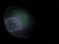
I don't want to insist, also because since I don't have the console here I can't be sure that everything is fine.
I want to specify, however, that this is the second time this has happened to me.
My installations are all the same, I attach photos.
To solve, the test time it happened to me I replaced the Rp2040, without touching the existing welds.
I specify that the replaced rp2040, I reused it once flashed again.
So I have my doubts, surely I can say that I have not encountered any problems with the fw 2.67, I don't know if it can be something from the fw with the rp2040 taken from aliexpress for a few euros / dollars.
I have installed 2 mosfets a few times, the other times always single mosfet, hooked on double capacitor.
Can't I do anything to reset the rp2040 gliches?

I mean, I'm confident in my job.
I might be wrong, but I doubt it, I think there is something firmware/hardware wrong.

(excuse my english by Google).
 

Attachments

  • IMG_20230517_202427.jpg
    IMG_20230517_202427.jpg
    1.2 MB · Views: 27
  • IMG_20230517_202431.jpg
    IMG_20230517_202431.jpg
    1.6 MB · Views: 26
  • IMG_20230517_220155.jpg
    IMG_20230517_220155.jpg
    2.8 MB · Views: 23
  • IMG_20230517_220235.jpg
    IMG_20230517_220235.jpg
    2.9 MB · Views: 22
  • IMG_20230517_220413.jpg
    IMG_20230517_220413.jpg
    2.4 MB · Views: 28
  • IMG_20230517_220415.jpg
    IMG_20230517_220415.jpg
    2.5 MB · Views: 29
  • IMG_20230517_201852_edit_34341095022884.jpg
    IMG_20230517_201852_edit_34341095022884.jpg
    889.2 KB · Views: 23
  • IMG_20230517_201902_edit_34305407036431.jpg
    IMG_20230517_201902_edit_34305407036431.jpg
    849.2 KB · Views: 23
  • IMG_20230517_195136.jpg
    IMG_20230517_195136.jpg
    2.4 MB · Views: 27
  • IMG_20230517_193539.jpg
    IMG_20230517_193539.jpg
    2.2 MB · Views: 31
  • IMG_20230422_201718.jpg
    IMG_20230422_201718.jpg
    3 MB · Views: 26
  • IMG_20230422_173304.jpg
    IMG_20230422_173304.jpg
    2.4 MB · Views: 30
  • IMG_20230422_173256.jpg
    IMG_20230422_173256.jpg
    1.9 MB · Views: 22
  • IMG_20230422_173238_edit_16228684526169.jpg
    IMG_20230422_173238_edit_16228684526169.jpg
    1.7 MB · Views: 17
  • IMG_20230517_231656.jpg
    IMG_20230517_231656.jpg
    2.3 MB · Views: 28
  • IMG_20230522_130501.jpg
    IMG_20230522_130501.jpg
    2.4 MB · Views: 29
  • IMG_20230529_130649.jpg
    IMG_20230529_130649.jpg
    1.7 MB · Views: 26
  • IMG_20230529_130636.jpg
    IMG_20230529_130636.jpg
    2 MB · Views: 18
  • IMG_20230529_130620_edit_348767869141572.jpg
    IMG_20230529_130620_edit_348767869141572.jpg
    1 MB · Views: 15
  • IMG_20230529_130550_edit_348753946636887.jpg
    IMG_20230529_130550_edit_348753946636887.jpg
    897.4 KB · Views: 20
  • IMG_20230529_130454.jpg
    IMG_20230529_130454.jpg
    2.3 MB · Views: 25
  • IMG_20230525_120307.jpg
    IMG_20230525_120307.jpg
    2.6 MB · Views: 29
  • IMG_20230525_120300.jpg
    IMG_20230525_120300.jpg
    2.5 MB · Views: 18
  • IMG_20230525_120217.jpg
    IMG_20230525_120217.jpg
    2.6 MB · Views: 23
  • IMG_20230525_120118.jpg
    IMG_20230525_120118.jpg
    2.4 MB · Views: 28
  • IMG_20230525_120112.jpg
    IMG_20230525_120112.jpg
    2.5 MB · Views: 28
  • IMG_20230522_130715_edit_137052571279607.jpg
    IMG_20230522_130715_edit_137052571279607.jpg
    549.3 KB · Views: 21
  • IMG_20230522_130638_edit_137079483063978.jpg
    IMG_20230522_130638_edit_137079483063978.jpg
    551.8 KB · Views: 16
  • IMG_20230522_130634_edit_137159722147820.jpg
    IMG_20230522_130634_edit_137159722147820.jpg
    591.8 KB · Views: 18
  • IMG_20230522_130613_edit_137188911445211.jpg
    IMG_20230522_130613_edit_137188911445211.jpg
    495.4 KB · Views: 20
  • IMG_20230422_172947.jpg
    IMG_20230422_172947.jpg
    1.7 MB · Views: 26
  • Like
Reactions: MoeXzl

Site & Scene News

Popular threads in this forum

General chit-chat
Help Users
    K3Nv2 @ K3Nv2: Lol rappers still promoting crypto