

You are using an out of date browser. It may not display this or other websites correctly.
You should upgrade or use an alternative browser.
You should upgrade or use an alternative browser.
Switch OLED teardown V1/V2
- Thread starter grubgrub
- Start date
- Views 214,347
- Replies 1,130
- Likes 10


They labeled it wrong. The upper D point is actually C. It connects to the DAT0 eMMC point.Thanks for your pictures. I'm currently doing this install but have a question. The flex cable at the top, why are there two D points? The one near the top I understand comes from the DAT0 adapter on the backside, what is the purpose of the other D point?
")
You have the SD with payload.bin plugged in?Hey all,
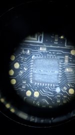
OLED switch with OLED chip (same as Sean222) What does a blue/purple light mean on the chip immediately after powering it on?
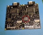
Check the CPU solder points (two of them) just check the connector on the right side bottom of the chip and probe for continuity of two points (since there are two points on CPU) with a multimeter.
Just a heads up for those with the 6 wire chip. There's an update to fix issues with SD Card compatibility and it has completely fixed the infinite glitching issue for me.
Just a heads up for those with the 6 wire chip. There's an update to fix issues with SD Card compatibility and it has completely fixed the infinite glitching issue for me.
For those that are looking for links and an install video for the 6 wire version.
Can you share details on this?Just a heads up for those with the 6 wire chip. There's an update to fix issues with SD Card compatibility and it has completely fixed the infinite glitching issue for me.

it's on the video posted exactly above your question.Can you share details on this?
My bad, getting a bit ahead of myself. Had watched that video just a while ago, but not quite that far through, as I've run into a problem.. I don't seem to get passed the yellow blinking LED "training" stage. Is this the "infinite glitching" they are referring to? Unfortunately my chip also just jumps to a red LED when connected to the USB cable. Any thoughts would be appreciated.
Edit: Also, I've tried disconnected the CPU ribbon cable, that causes instant red light. Also disconnected the ribbon and power cables, and the system turned on normally, so there are no massive shorts happening. Diode values seem decent.
Edit: Also, I've tried disconnected the CPU ribbon cable, that causes instant red light. Also disconnected the ribbon and power cables, and the system turned on normally, so there are no massive shorts happening. Diode values seem decent.
If you disconnect all the wires and connect the chip to your computer are you still getting red or yellow?My bad, getting a bit ahead of myself. Had watched that video just a while ago, but not quite that far through, as I've run into a problem.. I don't seem to get passed the yellow blinking LED "training" stage. Is this the "infinite glitching" they are referring to? Unfortunately my chip also just jumps to a red LED when connected to the USB cable. Any thoughts would be appreciated.
Edit: Also, I've tried disconnected the CPU ribbon cable, that causes instant red light. Also disconnected the ribbon and power cables, and the system turned on normally, so there are no massive shorts happening. Diode values seem decent.
I had an issue with it taking over 10 minutes to do the learning thing. This came down to me not having a good connection on either SP1/SP2 so I just resoldered them and touched up the CLK point and all was well.
They all seem to be reading decently except potentially the RST, getting conflicting results on searching this value. Should it read a diode value? Some say no. I don't seem to get anything even directly from the board, and that was one of the easier wires to get attached.
Edit: Tried disconnecting the RST point from the chip, no change in behavior. Not sure what the RST point does exactly...
Edit: Tried disconnecting the RST point from the chip, no change in behavior. Not sure what the RST point does exactly...
Last edited by ViOTeK,
Like I said, remove your chip from the console and plug into PC, do you get a red or yellow LED, if yellow, flash the latest fw. If it's red or anything else you probably have a bad or bricked chipThey all seem to be reading decently except potentially the RST, getting conflicting results on searching this value. Should it read a diode value? Some say no. I don't seem to get anything even directly from the board, and that was one of the easier wires to get attached.
Edit: Tried disconnecting the RST point from the chip, no change in behavior. Not sure what the RST point does exactly...
Since I don't have a board in front of me, would anyone be able to probe around on the board and find a spot where vol + and vol - would link up? I've had to reset my chip a couple times due to infinite glitching, linking the reset points to vol + and - may be a good idea, hold both on startup and it resets... assuming this would work.
Just tried, no go, still get a red light, after a quick single blue/purple blip.Like I said, remove your chip from the console and plug into PC, do you get a red or yellow LED, if yellow, flash the latest fw. If it's red or anything else you probably have a bad or bricked chip
Before that I also tried checking the cpu connections, one wasn't the greatest looking, re-did that, but no effect either.
Checking the other connections currently but they look pretty good, curious on my diode readings however as they are all a bit higher then in the video guide:
DAT0 = 970
CLK = 975
CMD = 965
RST = nothing with black on ground, reversing the polarity I see 455?
Edit: The above RST reading is right on the boards solder point, so maybe it's my meter, will check again tomorrow.
3.3v = 1142
GND = 0
Can anyone comment? Also, this is using an ancient crappy multimeter.. I'll be picking up a better one tomorrow and re-check.
About time to check out for the night, just glad it's not bricked, yet.
your rst definitely has issue, rest looks ok.Just tried, no go, still get a red light, after a quick single blue/purple blip.
Before that I also tried checking the cpu connections, one wasn't the greatest looking, re-did that, but no effect either.
Checking the other connections currently but they look pretty good, curious on my diode readings however as they are all a bit higher then in the video guide:
DAT0 = 970
CLK = 975
CMD = 965
RST = nothing with black on ground, reversing the polarity I see 455?
Edit: The above RST reading is right on the boards solder point, so maybe it's my meter, will check again tomorrow.
3.3v = 1142
GND = 0
Can anyone comment? Also, this is using an ancient crappy multimeter.. I'll be picking up a better one tomorrow and re-check.
About time to check out for the night, just glad it's not bricked, yet.
Thanks duder, Yeah I'm working on an updated oled install vid right now going over the various happenings in the Oled scene, (new chips, hwfly lite psa ect)It's this one. I cut off part of the flex PCB (the U shaped one) because it goes over a chip to reach the 3.3v/ground, thus it goes up in the air. After I cut it, that PCB flex piece lays FLAT
Without the USB debug port it's not easily flashable. You'll probably have to solder wires to the chip pins to flash it...
@Modzvilleusa does alot of installs, he's good. He also believes this version is poorly designed
Don't be fooled by the slick appearance of the dual flex cable. Everything about these chips is shittier than the other chips with the debug port.
Cpu cable is jank, dat0 adapter should be thrown in the trash and boot times are the worst.
It also can't be updated / flashed unlike the other variant. Just avoid this revision entirely and use the oled chip with the debug port / test pads to solder to.
Sounds like a bad chip. Assuming it's the 6 wire chip it should be yellowJust tried, no go, still get a red light, after a quick single blue/purple blip.
Before that I also tried checking the cpu connections, one wasn't the greatest looking, re-did that, but no effect either.
Checking the other connections currently but they look pretty good, curious on my diode readings however as they are all a bit higher then in the video guide:
DAT0 = 970
CLK = 975
CMD = 965
RST = nothing with black on ground, reversing the polarity I see 455?
Edit: The above RST reading is right on the boards solder point, so maybe it's my meter, will check again tomorrow.
3.3v = 1142
GND = 0
Can anyone comment? Also, this is using an ancient crappy multimeter.. I'll be picking up a better one tomorrow and re-check.
About time to check out for the night, just glad it's not bricked, yet.

Hello, just received my OLED chips and when connecting to the PC one goes straight to RED led and the other Yellow led.
the one with that goes straight to Red has a groove on one of the chips like its been dremeled.
I'm assuming its dead? what about the Yellow led one? should it not be Green or only when it's installed?
still waiting for my OLED Switch to arrive.
the one with that goes straight to Red has a groove on one of the chips like its been dremeled.
I'm assuming its dead? what about the Yellow led one? should it not be Green or only when it's installed?
still waiting for my OLED Switch to arrive.
Attachments

I would advise you to completely re-solder the cpu cable, because the red light appears when there is no cpu connectionBefore that I also tried checking the cpu connections, one wasn't the greatest looking, re-did that, but no effect either.
Similar threads
- Replies
- 0
- Views
- 268
- Replies
- 4
- Views
- 1K
- Replies
- 5
- Views
- 1K
- Replies
- 3
- Views
- 405
Site & Scene News
New Hot Discussed
-
-
26K views
Nintendo Switch firmware update 18.0.1 has been released
A new Nintendo Switch firmware update is here. System software version 18.0.1 has been released. This update offers the typical stability features as all other... -
20K views
The first retro emulator hits Apple's App Store, but you should probably avoid it
With Apple having recently updated their guidelines for the App Store, iOS users have been left to speculate on specific wording and whether retro emulators as we... -
19K views
TheFloW releases new PPPwn kernel exploit for PS4, works on firmware 11.00
TheFlow has done it again--a new kernel exploit has been released for PlayStation 4 consoles. This latest exploit is called PPPwn, and works on PlayStation 4 systems... -
19K views
Delta emulator now available on the App Store for iOS
The time has finally come, and after many, many years (if not decades) of Apple users having to side load emulator apps into their iOS devices through unofficial...by ShadowOne333 96 -
17K views
Nintendo officially confirms Switch successor console, announces Nintendo Direct for next month
While rumors had been floating about rampantly as to the future plans of Nintendo, the President of the company, Shuntaro Furukawa, made a brief statement confirming... -
17K views
Nintendo takes down Gmod content from Steam's Workshop
Nintendo might just as well be a law firm more than a videogame company at this point in time, since they have yet again issued their now almost trademarked usual...by ShadowOne333 123 -
14K views
A prototype of the original "The Legend of Zelda" for NES has been found and preserved
Another video game prototype has been found and preserved, and this time, it's none other than the game that spawned an entire franchise beloved by many, the very...by ShadowOne333 31 -
13K views
New static recompiler tool N64Recomp aims to seamlessly modernize N64 games
As each year passes, retro games become harder and harder to play, as the physical media begins to fall apart and becomes more difficult and expensive to obtain. The... -
13K views
Anbernic reveals specs details of pocket-sized RG28XX retro handheld
Anbernic is back with yet another retro handheld device. The upcoming RG28XX is another console sporting the quad-core H700 chip of the company's recent RG35XX 2024... -
12K views
Name the Switch successor: what should Nintendo call its new console?
Nintendo has officially announced that a successor to the beloved Switch console is on the horizon. As we eagerly anticipate what innovations this new device will...
-
-
-
245 replies
Name the Switch successor: what should Nintendo call its new console?
Nintendo has officially announced that a successor to the beloved Switch console is on the horizon. As we eagerly anticipate what innovations this new device will...by Costello -
213 replies
Nintendo officially confirms Switch successor console, announces Nintendo Direct for next month
While rumors had been floating about rampantly as to the future plans of Nintendo, the President of the company, Shuntaro Furukawa, made a brief statement confirming...by Chary -
123 replies
Nintendo takes down Gmod content from Steam's Workshop
Nintendo might just as well be a law firm more than a videogame company at this point in time, since they have yet again issued their now almost trademarked usual...by ShadowOne333 -
97 replies
The first retro emulator hits Apple's App Store, but you should probably avoid it
With Apple having recently updated their guidelines for the App Store, iOS users have been left to speculate on specific wording and whether retro emulators as we...by Scarlet -
96 replies
Delta emulator now available on the App Store for iOS
The time has finally come, and after many, many years (if not decades) of Apple users having to side load emulator apps into their iOS devices through unofficial...by ShadowOne333 -
84 replies
New static recompiler tool N64Recomp aims to seamlessly modernize N64 games
As each year passes, retro games become harder and harder to play, as the physical media begins to fall apart and becomes more difficult and expensive to obtain. The...by Chary -
82 replies
Nintendo Switch firmware update 18.0.1 has been released
A new Nintendo Switch firmware update is here. System software version 18.0.1 has been released. This update offers the typical stability features as all other...by Chary -
80 replies
TheFloW releases new PPPwn kernel exploit for PS4, works on firmware 11.00
TheFlow has done it again--a new kernel exploit has been released for PlayStation 4 consoles. This latest exploit is called PPPwn, and works on PlayStation 4 systems...by Chary -
74 replies
"Nintendo World Championships: NES Edition", a new NES Remix-like game, launching July 18th
After rumour got out about an upcoming NES Edition release for the famed Nintendo World Championships, Nintendo has officially unveiled the new game, titled "Nintendo...by ShadowOne333 -
71 replies
DOOM has been ported to the retro game console in Persona 5 Royal
DOOM is well-known for being ported to basically every device with some kind of input, and that list now includes the old retro game console in Persona 5 Royal...by relauby
-
Popular threads in this forum
General chit-chat
-
 K3Nv2
Loading…
K3Nv2
Loading… -
 DinohScene
Loading…That cat suit twink
DinohScene
Loading…That cat suit twink
-
-
-
-
-
-
-
-
-
-
-
-
-
-
-
-
-
-
-
-
-
@
K3Nv2:
Hm doing research quite possible my issue with this drive is bios related not detecting it fully
-
-
-
-