It’s fixed and already back to the customerlike i said u has a issue with eather ur soldering/wire is getting grounded check ur soldering and u will find the issue

It’s fixed and already back to the customerlike i said u has a issue with eather ur soldering/wire is getting grounded check ur soldering and u will find the issue
well why dont u let us know what the issue was so other people who have a same issue they maybe find the solutionIt’s fixed and already back to the customer
")
Hey well i did try to see all the questions that where asked when u released it but since u need to use a email to get further i stopped there mainly because its google Xd ( Privacy nerd here)
the survey is pretty interesting but there i one most important question u have left out and that is have u had any experience with repair/modding/soldering before.
because the thing is most of the people who do this install have very little to zero experience in soldering or repair.
therefor they barely know what they are doing and the install issue nr.1 is having almost none experience installing and not knowing the basics .
like i said plenty of times i have had all variant of switches hardware and version wise and never encountered an issue.
one example is Freelander(not trying to talk shit about u)
he has damaged somany switches while trying to mode by doing basic mistake (grinding on soldering point and other rookie mistakes)
thats why i say this survey is nice but not really what u need to see where the issues come frome (since thats the point of the survey correct?)
installing a pico doesnt take a expert but it does take some basic knowledge i mean sure a beginner can be lucky and get it done if he takes his time and has the correct equipment and knows how to use it.
but u did a nice job with u survey insteresting number i like that most people use mosfet instead of the finished product even though its a bit harder.
I like the idea, and if enough people take this survey I think we might get some insights on these 2-3 types of errors that we have been seeing recently.
I've done 13 installs by now (all models, 10 with pico, the other 3 with sx/hwfly but I redid those with pico aswell)
The only issue I faced was hwfly flex cable (for clk,cmd,rts) and (maybe) a shorted dat0 (not sure if this was the issue but i changed that aswell).
What I can see from reading this thread at least 2 times over is that after Pico debute on the scene alot of people built up the courage to try this mod because of the cheap price.
Younger people (most likely with less income) tend to buy Lite because of the price and portability, and I believe that this is the main reason we are seeing the spike in dead/damaged Lites; young unexperienced people trying to use a cheap mod to save some more money.
Having an oportunity to have limitless supply of games for aroud $10 is really tempting (because, let's be honest this is what this is about for the 95%).
People who bought a $400 console and $130 mod chip will either have some pro do the installation or they most likely know what they are doing before they decide to spend $130 on a modchip.
TL;DR
In the end, I don't wanna jinx my "luck" but I'm with @Dee87 on this one and I really think that in 99.5% of the cases it's installation issue (appart from the ones who used infamous 2.72fw) because there is just not that much hardware variation in switch models to account for such a different user experience during mod installation
try to add another resistor on dat0 then cmd.Hi guys, today I received a switch victim of an incorrect picofly DIY installation.
I immediately identified the problem (it was very evident) as the CPU cable was shorted to ground.
The console did not turn on.
I just partially got it working again.
The current conditions are as follows:
1) The console can start hekate but it doesn't start in OFW, Nintendo appears and then black screen. To start hekate again, I have to disconnect the battery.
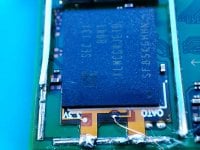
2) I get slow emmc error, but I think it's an EMMC hardware error, as I can backup boot0,1 and also all emmc. However, I cannot save the keys, I receive an error (photo attached).
3) I created emummc and it starts up, but it doesn't wake up from rest mode.
My question is is there any way to reset mmc? (I have a donor switch, in case I could use the mmc.)
Can I wake from sleep in emummc?
I attach all the photos.
Thanks for your support.
Because I never really figured out what the issue was. I went from double mosfet to flex to single mosfet. Even the single mosfet was giving problems. It was covered of course. But it’s been acting fine so I gave it back to the customer. I’m still unsure. I just did a v2 with a single mosfet, took an hour, and it’s running perfect so idk.well why dont u let us know what the issue was so other people who have a same issue they maybe find the solution
Before adding resistors, it should still boot into OFW or am I wrong?try to add another resistor on dat0 then cmd.
Yes, to narrow it down into any instalation issue then you must clean all and try to restore ofw full funcionality first. After that you can redo carefully for this time.Before adding resistors, it should still boot into OFW or am I wrong?
In Emummc instead, once the console goes into standby, it is not possible to wake it up.
My theory is that shorting the 15 CPU wire corrupted or damaged the mmc.
Now will I try resistors first or mmc unbrick first?

=* means the pico doesn't read the voltage in the range 1.6-2.0vHi guys, quick question about an OLED RP2040-zero install. Everything seems to be fine, diode mode test gives good values, but on boot I get =* (no dat0) and it goes directly to OFW. dat0 shows continuity to the RP2040 with good values though...
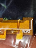
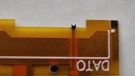
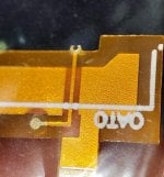
The supplier I used sent a janky OATO flex for the emmc and when installed, it is offset to the right and the contact point seems to have a really bad shape but does seem to contact the correct pin. Could it be a bad dat0 contact, or is there a possibility for another issue? I have the 4 anchor point dat0 on it's way but if there's anything else to check before swapping the adaptors I'm open for ideas.
Voltage from emmc? I checked the resistors, all read 48 still with no shorts. dat0 line shows a strong connection. No wiggle at all on the adaptor. Also, it stopped giving =* when I just checked and now gives =** (emmc initi failure).=* means the pico doesn't read the voltage in the range 1.6-2.0v
So i am sure there is disconnection somewhere on the dat0 line.
Maybe the 47ohms resistor burned?
Voltage from emmc? I checked the resistors, all read 48 still with no shorts. dat0 line shows a strong connection. No wiggle at all on the adaptor. Also, it stopped giving =* when I just checked and now gives =** (emmc initi failure).
Hm, CMD and CLK are the two I have the most confidence in. Honestly, I think the 'OATO' adaptor is just bad and others have recommended avoiding it, the claw contact looks bad, and there's a high chance it's just not making good enough contact, which could result in the voltage error. So far, the board still boots into OFW so the emmc is still good.View attachment 377262
If you know embedded, this code simply check the voltage. The =* error is simply the rp2040 read the gpio pin on dat0 voltage and is not around 1.8 +- 0.2V.
=** is different error. The d0 voltage check are passed means it connected. This could be lot of scenario. I am not focused now, afraid giving wrong analyze.
If you said is true, when you check the error change from =* to =** then the connection on your d0 line is unstablle. Please make sure its okay first (before connecting power or turn it on). Because one mistake in there could corrupt your emmc, which lead to blue screen or black screen which will be very difficult to analyze and solved.
Just cheap analyze (i am not thourough in here), initialization error means that that rp2040 couldn't read emmc initialization activity in CMD line which supposed to be happening after a Reset. It could be the CMD line is unstable, or CLK line is unstable.
It could be a short on dat0, in my experience if the adapter makes a short under emmc it still gives the correct diode value. I would cut the left side of the dat0 adapter (like abal1000x did earlier) or just wait for the good one.Hm, CMD and CLK are the two I have the most confidence in. Honestly, I think the 'OATO' adaptor is just bad and others have recommended avoiding it, the claw contact looks bad, and there's a high chance it's just not making good enough contact, which could result in the voltage error. So far, the board still boots into OFW so the emmc is still good.
I'll wait for the good DAT0 adaptor to arrive in a day or so and give that one a try and see how it turns out first. I don't want to have to remove the mask I put on the CLK point.
Yeah the old one isn't viable now, one of the ground 'legs' tore when I tried to desolder it to make the changeIt could be a short on dat0, in my experience if the adapter makes a short under emmc it still gives the correct diode value. I would cut the left side of the dat0 adapter (like abal1000x did earlier) or just wait for the good one.
Just check the photo and you will see why this is possible
The newer 4 anchor point one is hitting my mailbox any day now so I'll just use that. Thanks!What exactly is the blink code? The duration is important. It's the yellow flashes and = is long flash * is short flash. It will show the code twice after whatever error happens.installed a picofly in a oled switch but it refuses to boot into hekate/no sd screen.
flashes blue and then 3x3 times yellow and stops blinking = black screen. when clk is removed the switch bootes into ofw. red that blinking yellow means dat0 issue. but i have .7v on dat 0 in diode mode. its not the first time i installed modchips. had many sxcore/hwfly installations on oled switch. any ideas?
it flashes 1xblue(long) 3x yellow(long, short, short, short) then stops flashingWhat exactly is the blink code? The duration is important. It's the yellow flashes and = is long flash * is short flash. It will show the code twice after whatever error happens.
=*** eMMC init failureit flashes 1xblue(long) 3x yellow(long, short, short, short) then stops flashing