Hacking Hardware Picofly - a HWFLY switch modchip

FreeLander

Well-Known Member
Member
Joined
Apr 6, 2023
Messages
350
Trophies
0
Age
35
XP
467
Country
United States
and with no SD card inserted you get a NO SD CARD screen?
Now I'm getting black screen with ==*. I've had this exact thing happening to me on a Lite. First it won't boot with SD card inserted and after re-soldering everything, blue screen.

Any idea why this keeps happening is massively appreciated.
 

lightninjay

Well-Known Member
Member
Joined
Mar 28, 2023
Messages
560
Trophies
0
Age
31
XP
1,371
Country
United States
Now I'm getting black screen with ==*. I've had this exact thing happening to me on a Lite. First it won't boot with SD card inserted and after re-soldering everything, blue screen.

Any idea why this keeps happening is massively appreciated.
Your LED code seems to indicate an issue with your MOSFETS, mind taking a clear photo of your mosfet install?
 

FreeLander

Well-Known Member
Member
Joined
Apr 6, 2023
Messages
350
Trophies
0
Age
35
XP
467
Country
United States
Your LED code seems to indicate an issue with your MOSFETS, mind taking a clear photo of your mosfet install?
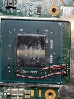
I figured as much, but the install looks clean to me.
This scenario happened twice and I won't be able to stop it if I didn't know what's wrong, it goes like this:
Switch works fine after install ( NO SD card logo)
I insert an SD card and get a black screen
I have to press power button for 10 second to get the no sd card logo again.

The moment I start twerking with it, ( sometimes as much as re-opening the case) I get a blue screen and that's it.
Removing all wires doesn't help.

What do I keep killing the CPU? Is it related to my MOSFET soldering. This happened to me on a Lite, OLED, and now a V1.

P.S this pic was taken before I masked everything with solder mask.

Please @Dee87 and @QuiTim @deeps @Adran_Marit @bilalhassan341 if you could troubleshoot this for me.
 

Attachments

  • IMG_7201.JPG
    IMG_7201.JPG
    1.5 MB · Views: 57
Last edited by FreeLander,
  • Sad
Reactions: bilalhassan341

lightninjay

Well-Known Member
Member
Joined
Mar 28, 2023
Messages
560
Trophies
0
Age
31
XP
1,371
Country
United States
I figured as much, but the install looks clean to me.
This scenario happened twice and I won't be able to stop it if I didn't know what's wrong, it goes like this:
Switch works fine after install ( NO SD card logo)
I insert an SD card and get a black screen
I have to press power button for 10 second to get the no sd card logo again.

The moment I start twerking with it, ( sometimes as much as re-opening the case) I get a blue screen and that's it.
Removing all wires doesn't help.

What do I keep killing the CPU? Is it related to my MOSFET soldering. This happened to me on a Lite, OLED, and now a V1.

P.S this pic was taken before I masked everything with solder mask.
Try changing the ground for the mosfets from the pad on the APU to something like the APU shield. Also, your left capacitor looks as if the solder joint could be made a little better.

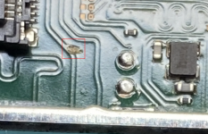
Also, what's going on with this trace?
TraceBooger.png
 

FreeLander

Well-Known Member
Member
Joined
Apr 6, 2023
Messages
350
Trophies
0
Age
35
XP
467
Country
United States
Try changing the ground for the mosfets from the pad on the APU to something like the APU shield. Also, your left capacitor looks as if the solder joint could be made a little better.
Sorry I removed everything and I'm still getting a blue screen. I figured it's dead and done and now I'm just focusing on knowing the reason and avoiding it.

Could the grounding, or left cap soldering cause a blue screen? Why after SD card insertion, why not immediately blue screen?
Post automatically merged:

Try changing the ground for the mosfets from the pad on the APU to something like the APU shield. Also, your left capacitor looks as if the solder joint could be made a little better.

Also, what's going on with this trace?
View attachment 374277
Good catch! didn't see it. Will look into it.
 

lightninjay

Well-Known Member
Member
Joined
Mar 28, 2023
Messages
560
Trophies
0
Age
31
XP
1,371
Country
United States
Sorry I removed everything and I'm still getting a blue screen. I figured it's dead and done and now I'm just focusing on knowing the reason and avoiding it.

Could the grounding, or left cap soldering cause a blue screen? Why after SD card insertion, why not immediately blue screen?
Blue screens are APU/RAM issues typically, but if you accidentally corrupted your NAND (Bad wiring, wrong resistor values on specific lines, wires disconnecting while "twerking" with things), you could potentially get a blue screen with no picofly installed. The picofly being properly installed should at least let you boot to Hekate (with a properly formatted SD card) and restore a nand/boot0/boot1 backup (if you have one) or rebuild a new nand (without online functionality) if you don't have a backup.
 
  • Love
Reactions: LogicalMadness

FreeLander

Well-Known Member
Member
Joined
Apr 6, 2023
Messages
350
Trophies
0
Age
35
XP
467
Country
United States
Blue screens are APU/RAM issues typically, but if you accidentally corrupted your NAND (Bad wiring, wrong resistor values on specific lines, wires disconnecting while "twerking" with things), you could potentially get a blue screen with no picofly installed. The picofly being properly installed should at least let you boot to Hekate (with a properly formatted SD card) and restore a nand/boot0/boot1 backup (if you have one) or rebuild a new nand (without online functionality) if you don't have a backup.
Thanks. The trace was just some dirt. Is there any chance that poor MOSFET soldering could result in a blue screen. What I fail to understand is that this happens ALWAYS after inserting SD card. If I had poor wiring somewhere why am I still getting a no sd card.
 

Attachments

  • 2EFD3387-B15B-4D53-A7B4-C3289483C02F.jpeg
    2EFD3387-B15B-4D53-A7B4-C3289483C02F.jpeg
    952.3 KB · Views: 54
  • Like
Reactions: Danook28

lightninjay

Well-Known Member
Member
Joined
Mar 28, 2023
Messages
560
Trophies
0
Age
31
XP
1,371
Country
United States
Thanks. The trace was just some dirt. Is there any chance that poor MOSFET soldering could result in a blue screen. What I fail to understand is that this happens ALWAYS after inserting SD card. If I had poor wiring somewhere why am I still getting a no sd card.
As you mentioned in your own post, you only get a "NO SD CARD" screen until you start "twerking" with it. If your soldering joints are making continuity, but are weak, then the glitch could work, and then disconnect while in operation, which could cause any number of strange behaviors, not the least of which could be a corrupt nand.

I know you are frustrated, but please do not blame the mod, as there have been countless successful installations to this point. Always assume that we (everyone doing this mod), the installer, are the ones at fault when something goes wrong. It seems like you want to find out what you've done wrong, but you are still fairly married to the idea that your install was "perfect". As I've said before, if an install is perfectly done, you wouldn't be posting here on these forums.
 

FreeLander

Well-Known Member
Member
Joined
Apr 6, 2023
Messages
350
Trophies
0
Age
35
XP
467
Country
United States
As you mentioned in your own post, you only get a "NO SD CARD" screen until you start "twerking" with it. If your soldering joints are making continuity, but are weak, then the glitch could work, and then disconnect while in operation, which could cause any number of strange behaviors, not the least of which could be a corrupt nand.

I know you are frustrated, but please do not blame the mod, as there have been countless successful installations to this point. Always assume that we (everyone doing this mod), the installer, are the ones at fault when something goes wrong. It seems like you want to find out what you've done wrong, but you are still fairly married to the idea that your install was "perfect". As I've said before, if an install is perfectly done, you wouldn't be posting here on these forums.
I agree. I also had a number of successful mods with Picfly, will never take that for granted. I'll never blame the mod, I'm 100% sure if you were watching me while doing the install, you would have caught something that would prevent this from happening.
Keeps moving forward and learning.
 

NooBziN

Well-Known Member
Member
Joined
Apr 28, 2016
Messages
176
Trophies
0
Age
38
XP
458
Country
Brazil
you mean 2.74.

and yes, this is the slowest glitching switch that has passed through my hands yet, out of about 12. most others glitch almost instantly
I just updated to 2.74 still same time 1 to 2s no change
it gets to be faster than any HWFLW model:rofl2:
 

cgtchy0412

Well-Known Member
Member
Joined
Apr 26, 2023
Messages
286
Trophies
0
Age
41
XP
431
Country
Indonesia
Type wier you use and that wier hold glue you do job very nice brother.
Its common wire wrapping awg30, its fit nicely through emmc point hole, thats why my V2 is the easiest. Almost guaranted perfect solder on emmc without any hassle.
I just updated to 2.74 still same time 1 to 2s no change
it gets to be faster than any HWFLW model:rofl2:
Seriously, this obsession with glitch time is kinda useless, as long as it takes unser 5s its perfect, thats the expected time an average person staring bsod screen without taking notes after they press power button.
And how many times a week that you need to restart/boot ? My kids never restart in weeks, i always told them to just use sleep and charge after low battery warning.
 
  • Like
Reactions: QuiTim and deeps

Razorbacktrack

Well-Known Member
Member
Joined
Aug 8, 2013
Messages
106
Trophies
1
Age
30
XP
378
Country
Italy
Switch Lite, SDA/SCL connected. I don't have the "no boot" or "very slow boot" problem with standard 2.74 fw, but I got better boot times with "2.74 w/o i2c" fw
 

deeps

Well-Known Member
Member
Joined
Jul 3, 2007
Messages
447
Trophies
1
XP
1,236
Country
Switch Lite, SDA/SCL connected. I don't have the "no boot" or "very slow boot" problem with standard 2.74 fw, but I got better boot times with "2.74 w/o i2c" fw

that's because the low-power mode that you achieve by using sda/scl makes the glitch take longer to succeed. you should only connect sda/scl if you really have to. the 2.74 without i2c doesn't use the sda/scl pins which is why it's faster.
 
  • Like
Reactions: Razorbacktrack

NooBziN

Well-Known Member
Member
Joined
Apr 28, 2016
Messages
176
Trophies
0
Age
38
XP
458
Country
Brazil
Its common wire wrapping awg30, its fit nicely through emmc point hole, thats why my V2 is the easiest. Almost guaranted perfect solder on emmc without any hassle.

Seriously, this obsession with glitch time is kinda useless, as long as it takes unser 5s its perfect, thats the expected time an average person staring bsod screen without taking notes after they press power button.
And how many times a week that you need to restart/boot ? My kids never restart in weeks, i always told them to just use sleep and charge after low battery warning.
for you who are a common user, you don't need
Since I work with reverse engineering, I keep restarting constantly to test :wink:
 
  • Wow
Reactions: LogicalMadness

blackheartme

Well-Known Member
Newcomer
Joined
May 28, 2021
Messages
51
Trophies
0
Age
35
XP
276
Country
Indonesia
ill admit OLED is just another different beast :rofl2:, massive wall compared to v1,v2 lite, especially that one scratch point takes time to do, not for first timer:bow:
 
  • Like
Reactions: QuiTim

abal1000x

Well-Known Member
Member
Joined
Jun 5, 2022
Messages
1,059
Trophies
0
XP
1,364
Country
Gaza Strip
  • Like
Reactions: NooBziN

mlucianoeze

Member
Newcomer
Joined
May 28, 2023
Messages
9
Trophies
0
Age
22
XP
29
Country
Argentina
Hello there! I'm trying to install picofly on a v2 with a Raspberry Pi Pico board.

I started this project a few weeks ago, when RGB LED was the only possible way to get error codes, so my board is on version v2.67. The thing is I cannot update the board because is already trimmed and I lost the USB port. This means I'm not able to get pulse error codes, and just RGB ones. The other problem is that Pi Pico board does not support the RGB LED so I'm stuck with its on-board LED.

I finished the setup today (with no success), using two IRFHS8342 MOSFETs, one for each cap, and every eMMC cable soldered to the eMMC board itself, except for RST, which is soldered to the switch motherboard. I tested every connection I could from the eMMC with its motherboard counterpart and they're all fine. I also tested each MOSFET and they also look really good. All I get is a small blink from the on-board LED (which remember, it's not RGB and I don't have the latest firmware either, so that tells me nothing), and after that blink it boots normally to OFW.

I wanted to try two things:

First, update the Pi Pico through SWD, so I can flash it with no need of the USB port. The problem here: you need to provide an ELF file through SWD, a UF2 won't work, and as I can see from GitHub, @rehius is not building the UF2 file with standard Raspberry Pi tools, but with a custom Python script, so I have no clue on how to build the ELF file by myself.

Second, I wanted to reset statistics to try from scratch, but I don't know how to do it using a Pi Pico board. I tried resetting the board on the joycon logo as someone suggested here (RUN pin to GND), but it didn't work. I want to reset them because before finishing, I've been testing the board alone and I'm worried about having corrupted statistics, but actually I don't know if the issue is with my wiring or not.

If I cannot do any of those, I'll have to go buy a new Pi Pico, flash the latest firmware with pulse error codes and trim it to resolder everything. I don't want to do this yet because it would require a ton of work: from the board cutting itself to the resoldering of EVERYTHING. I would like to avoid this as much as I can if possible.

Anyway, any clue would be really appreciated. :)
 

cgtchy0412

Well-Known Member
Member
Joined
Apr 26, 2023
Messages
286
Trophies
0
Age
41
XP
431
Country
Indonesia
Hello there! I'm trying to install picofly on a v2 with a Raspberry Pi Pico board.

I started this project a few weeks ago, when RGB LED was the only possible way to get error codes, so my board is on version v2.67. The thing is I cannot update the board because is already trimmed and I lost the USB port. This means I'm not able to get pulse error codes, and just RGB ones. The other problem is that Pi Pico board does not support the RGB LED so I'm stuck with its on-board LED.

I finished the setup today (with no success), using two IRFHS8342 MOSFETs, one for each cap, and every eMMC cable soldered to the eMMC board itself, except for RST, which is soldered to the switch motherboard. I tested every connection I could from the eMMC with its motherboard counterpart and they're all fine. I also tested each MOSFET and they also look really good. All I get is a small blink from the on-board LED (which remember, it's not RGB and I don't have the latest firmware either, so that tells me nothing), and after that blink it boots normally to OFW.

I wanted to try two things:

First, update the Pi Pico through SWD, so I can flash it with no need of the USB port. The problem here: you need to provide an ELF file through SWD, a UF2 won't work, and as I can see from GitHub, @rehius is not building the UF2 file with standard Raspberry Pi tools, but with a custom Python script, so I have no clue on how to build the ELF file by myself.

Second, I wanted to reset statistics to try from scratch, but I don't know how to do it using a Pi Pico board. I tried resetting the board on the joycon logo as someone suggested here (RUN pin to GND), but it didn't work. I want to reset them because before finishing, I've been testing the board alone and I'm worried about having corrupted statistics, but actually I don't know if the issue is with my wiring or not.

If I cannot do any of those, I'll have to go buy a new Pi Pico, flash the latest firmware with pulse error codes and trim it to resolder everything. I don't want to do this yet because it would require a ton of work: from the board cutting itself to the resoldering of EVERYTHING. I would like to avoid this as much as I can if possible.

Anyway, any clue would be really appreciated. :)
Just get another pi pico, flash 2.74, and this time just remove the transistor for dat0 solder point in pico board, then assembled all the wire, then power on.. if like you said that your switch board soldering in fine then it should boot to sdcard screen.
Pi Pico is a rather tricky, but ive done multiple units with Pi Pico and in the process ive lost/burn/broke 4 pico boards.
 
  • Like
Reactions: Danook28

Site & Scene News

Popular threads in this forum

General chit-chat
Help Users
  • No one is chatting at the moment.
    Psionic Roshambo @ Psionic Roshambo: I did use a bot for Diablo III though but no ban there lol