Just wanted to give an update on my Pokemon Let's Go patched V1. I had to disassemble and reassemble a few times to get everything to fit properly in the case and not ruin the glitching process.
Still had a few loose-ish solder points apparently, as when I went and retouched some areas after checking for continuity, I managed to get the Hekate ipl consistently to load.
Thanks to everyone involved in this project, including all the brave souls willing to be on the front line of testing out the newest hardware mod to the scene.
I would post some photos, but I'm too busy reading all the things about how to load different software on this sucker now, ENDLESS POSSIBILITIES!

EDIT to add photos:
View attachment 362961
I ended up doing the same mod as a few other folks earlier in the forum of installing a ps4 controller flex connector in the stead of the USB C that gets removed. This was my second or third attempt at stripping the flex cable and getting to the pins without bending them. I used a razor blade to scrape the surface away and reveal fresh copper in the flex cable, then tinned them which causes the rest of the flex cable to melt away. Then I tinned the pins on the USB C port and held the flex cable down with some electrical tape and lined up the usb-c with tweezers while hitting the pins with my hot-air station. Once I had a solid connection, I used UV-cure resin to reinforce the solder joint. It is sitting on an American Dime for scale.
View attachment 362962
This is what the CPU wire looks like when attached using 30awg Kynar. Kynar is not LARGE wire by any means, but these components are certainly a little more challenging with 30awg wire wanting to move... we'll get to that in a second. That is the head of a Q-Tip for referenc scale.
View attachment 362969
After seeing where the ground points are, I decided on the easy and sure-fire way out of just ground to the leg of the USB-C port.
View attachment 362970
The 3.3v line was the first tiny spot that I went for, and this was where I learned how valuable uv-cure resin and a UV handheld laserpointer can be to keeping your wires held in place after soldering.
View attachment 362963
These are the Dat0 and Clk pins prior to getting a UV-cure resin treatment to more permanently hold the wire leads down.
View attachment 362968
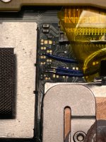
Here are my RST and CMD lines along with the two previous pins after being cured with resin. There is also a wooden toothpick for scale.
View attachment 362964
This was while things were looking good. I had just gotten the mosfet situated in place on the left cap. As I was feeding the CPU wire through the APU shielding, I jiggled the backend a little too hard and ripped the capacitor clean off the pads, taking the pad closest to the APU completely off, and de-tinning the ground pad... Recovery involved sulking a little, making sure my console still booted to OFW, and then pressing onward to the following...
View attachment 362966
This abomination is layers of resin used to both mask solder joints from bridging, and to prevent my clumsy self from ripping off my last remaining lifeline to glitching this switch. Am I proud of it? Oddly yes, a little. I had to cut part of my APU shield to make sure this doesn't get disturbed, but WORTH IT. It's nearly unrecognizable at this point, but that is the same MOSFET from earlier on in this post.
View attachment 362965
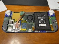
Here was my bodged long-wire setup to prove that the pico would work for me. This is the second rp2040 zero that I installed, which ultimately led me to check every last one of my solder joints again. After confirming I could glitch my switch, I swapped back to my flex-cable modded picofly to be able to fully install it with no bulge, but still be able to easily update it through USB to at least make the jump to 2.6 when it's released. As everyone else is hoping, we'll hopefully be able to remotely update future firmwares through the switch (if even needed).
Thank you again for all the insight, and I hope this can provide even a little inspiration (or even an eye-opener to how small-scale this solder job is) for anyone seeking to do this kind of mod to their own switch. It's a real chore, even if you are good at soldering. Things can and will go wrong, even if you do everything right. Just be prepared to fix things if you mess them up. As others have stated, you can ruin your console if you mess up installing these kinds of mods (and several members have openly mentioned that they have learned from losing consoles as experience) but with careful planning and the right tools, you too can own a picofly modded switch.


 Next time i will try with a 256gb but its much more expensive.