You are using an out of date browser. It may not display this or other websites correctly.
You should upgrade or use an alternative browser.
You should upgrade or use an alternative browser.
Picofly AIO Thread
- Thread starter Adran_Marit
- Start date
- Views 542,386
- Replies 3,380
- Likes 60
fuse burning only happens on major version updates afaik, so the next one would be 17.0.x. 16.0.3 doesn't cause any issues.So now that 16.0.3 is out...whats the proper way to update OFW when considering fuse burning? Thanks!
I just meant for updating in general, but yeah, fuses likely aren't an issue with this release.fuse burning only happens between major version updates afaik, so 17.0.x will be the next fuse burner. 16.0.3 doesn't cause any issues.
sorry, hamburger fingers, quoted wrong postI just meant for updating in general, but yeah, fuses likely aren't an issue with this release.
Hey everyone, could use some help with my Switch Lite. I posted in the other thread, but I only got a reply from one person, and it quickly got buried.
I installed the picofly, first try everything booted. Unfortunately the wires I used for the drain of the mosfets to the CPU caps were too thin, so when I reassembled my switch and powered on again, one of them burnt. I opened it back up, disassembled things, and found that burnt wire. I replaced it, had the same issue again (I thought maybe it shorted from something else the first time around), and that's when I realized the wires were probably too thin. I replaced the wires to the two CPU caps, and replaced the mosfets as well just in case.
Now when I power the switch on, I get the blue --> green LED, but I have no display. On my first boot I got to the "No SD Card" screen, but since then I've had no display. I triple checked all of my connections and everything seems good. The RP2040 Zero is getting 3.3v, and I can see ~1v on the CPU caps that I've soldered wires to. I did have to replace the right CPU cap, the thicker enameled wire I soldered to it ended up breaking it off. The pads were still good, and luckily I had some 0201 100nF caps on hand.
I used a light to see if maybe I lost backlight, but there is no picture on the screen at all. I checked the cables for the digitizer and display, they both look good. There was one spot on the display cable that looked a bit odd, so I scratched away the coating, but the copper looked good to me. I scratched a bit more off and added some solder just in case, but no change there either. I tried unplugging the daughter board and booting by connecting to power, no change. I made sure nothing is being shorted - I used enameled wire throughout the whole modification, so no wires are making contact with something they shouldn't, or with each other.
Anyone have any idea where I should go from here? To me it seems like the switch isn't booting fully, but I have no clue why...
Try troubleshooting using this postHey everyone, could use some help with my Switch Lite. I posted in the other thread, but I only got a reply from one person, and it quickly got buried.
I installed the picofly, first try everything booted. Unfortunately the wires I used for the drain of the mosfets to the CPU caps were too thin, so when I reassembled my switch and powered on again, one of them burnt. I opened it back up, disassembled things, and found that burnt wire. I replaced it, had the same issue again (I thought maybe it shorted from something else the first time around), and that's when I realized the wires were probably too thin. I replaced the wires to the two CPU caps, and replaced the mosfets as well just in case.
Now when I power the switch on, I get the blue --> green LED, but I have no display. On my first boot I got to the "No SD Card" screen, but since then I've had no display. I triple checked all of my connections and everything seems good. The RP2040 Zero is getting 3.3v, and I can see ~1v on the CPU caps that I've soldered wires to. I did have to replace the right CPU cap, the thicker enameled wire I soldered to it ended up breaking it off. The pads were still good, and luckily I had some 0201 100nF caps on hand.
I used a light to see if maybe I lost backlight, but there is no picture on the screen at all. I checked the cables for the digitizer and display, they both look good. There was one spot on the display cable that looked a bit odd, so I scratched away the coating, but the copper looked good to me. I scratched a bit more off and added some solder just in case, but no change there either. I tried unplugging the daughter board and booting by connecting to power, no change. I made sure nothing is being shorted - I used enameled wire throughout the whole modification, so no wires are making contact with something they shouldn't, or with each other.
Anyone have any idea where I should go from here? To me it seems like the switch isn't booting fully, but I have no clue why...
https://gbatemp.net/threads/sx-lite...he-screen-doesnt-turn-on.571362/#post-9172025
I had a similar issue when hacking my gf's switch lite, and though nothing was obviously damaged upon visual inspection, one of those points didn't have continuity for me. I run some magnet wire between the two that weren't connected and it brought the screen back to life.
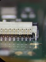
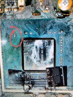
Oh man, thank you for linking this! Turns out I was missing continuity between the yellow points on both ends. The cable itself was fine, but the connector had a bent pin on the inside. Tried to bend it back, but it ended up breaking off. I ran a jumper, and just like that it turns on again!Try troubleshooting using this post
https://gbatemp.net/threads/sx-lite...he-screen-doesnt-turn-on.571362/#post-9172025
I had a similar issue when hacking my gf's switch lite, and though nothing was obviously damaged upon visual inspection, one of those points didn't have continuity for me. I run some magnet wire between the two that weren't connected and it brought the screen back to life.
Attachments
Well done, glad I could help. Ironically, the guy that thread was trying to help ended up just selling his broken switch and buying another instead of attempting repair lolOh man, thank you for linking this! Turns out I was missing continuity between the yellow points on both ends. The cable itself was fine, but the connector had a bent pin on the inside. Tried to bend it back, but it ended up breaking off. I ran a jumper, and just like that it turns on again!
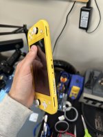
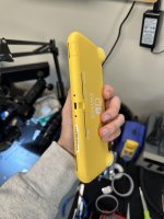
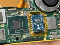
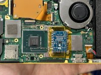
And with that, my switch lite install is complete! Took far too long, and this was before I swapped out the CPU wires with something a little bit thicker, but it looks effectively the same as these photos. Can't even tell it's inside 
Attachments
Only slightly concerned... did you completely remove the APU shield and not reapply it before closing back up? I only ask due to the placement of your mosfets ON the shield frame.And with that, my switch lite install is complete! Took far too long, and this was before I swapped out the CPU wires with something a little bit thicker, but it looks effectively the same as these photos. Can't even tell it's inside
I've never attempted to put the heatpipe directly onto the APU, so I'm not sure whether or not this presents an issue, but hope it all works out for you!
I switch the placement of the pico from right to left. Its better in the left part, the aluminium shield is perfectly fit.And with that, my switch lite install is complete! Took far too long, and this was before I swapped out the CPU wires with something a little bit thicker, but it looks effectively the same as these photos. Can't even tell it's inside
What do you guys think about this video. Go to 3:20...he's talking about using the sysnand to update OFW.I just meant for updating in general, but yeah, fuses likely aren't an issue with this release.
What do you guys think about this video. Go to 3:20...he's talking about using the sysnand to update OFW.
Don't follow youtube video, follow a written guide instead.
Oh man, thank you for linking this! Turns out I was missing continuity between the yellow points on both ends. The cable itself was fine, but the connector had a bent pin on the inside. Tried to bend it back, but it ended up breaking off. I ran a jumper, and just like that it turns on again!
So it was the backlight then.
Were you powering it on w\ the buttons or shorting the pins? I assumed that you were using the buttons, thus, a much lower chance of the daughter board needing closer inspection. I'm confused on why this was touched at all for a PFly install... Especially you @lightninjay
Oh, that's the backlight line? Weird then, because I couldn't see anything on the screen with a light pointed at it. I was using the button. The battery connector is right under the connector that got damaged, and I had to undo it quite a bit. I'm surprised that one of the inner pins got bent, I was always very careful with the connector. But at least the issue is solved! It's my personal switch so I just ran a jumper, if it was someone else's I would do a connector swap and no jumper would be needed.So it was the backlight then.
Were you powering it on w\ the buttons or shorting the pins? I assumed that you were using the buttons, thus, a much lower chance of the daughter board needing closer inspection. I'm confused on why this was touched at all for a PFly install... Especially you @lightninjay
Post automatically merged:
I cut the shield, removed the half that sits on top of the memory. It's not cooling it anyways, so it's basically useless. I could have fit the picofly on top of the shield in the same spot, but this allowed it to be slightly lower, so everything fits a bit betterOnly slightly concerned... did you completely remove the APU shield and not reapply it before closing back up? I only ask due to the placement of your mosfets ON the shield frame.
I've never attempted to put the heatpipe directly onto the APU, so I'm not sure whether or not this presents an issue, but hope it all works out for you!
Hi....i installed picifly on a lite switch....everything ok but when i was turning on got a fuckin bsod...i dont even put a sd card... the first time got no sd...after that just blue screen? Am i bricked it? Is there any solution...the console is brand new
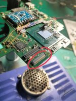
Oh, so it WAS the ribbon that was causing 'no backlight' (I see your pic now, the only thing it COULD have been is the backlight pins, guess I needed to specify the "connectors" of the 'main ribbon' as well?), you didn't actually touch the daughter board. The discoloration of the ribbon was due to the pins being out of whack, more than likely.
@lightninjay's link goes str8 to a pic of the daughter's backlight connector and I thought that was your issue since you gave credit to Jay for helping you Hence, the confusion as to why the daughter board was touched at all.
I currently have a bsod that I think is just because I was careless and swiped a cap off the APU. Will let you know how the fix goes.
I've fixed bsod before by bending the Switch back into shape and reflowing the APU. I think I've read that it could be the ram too, another reflow\reball. Otherwise, dead Switch.
@lightninjay's link goes str8 to a pic of the daughter's backlight connector and I thought that was your issue since you gave credit to Jay for helping you
Post automatically merged:
Double check everything related to the APU. All caps, look for solder balls, bridging, etc.Hi....i installed picifly on a lite switch....everything ok but when i was turning on got a fuckin bsod...i dont even put a sd card... the first time got no sd...after that just blue screen? Am i bricked it? Is there any solution...the console is brand new
I currently have a bsod that I think is just because I was careless and swiped a cap off the APU. Will let you know how the fix goes.
I've fixed bsod before by bending the Switch back into shape and reflowing the APU. I think I've read that it could be the ram too, another reflow\reball. Otherwise, dead Switch.
Attachments
Last edited by LogicalMadness,
My screen on the lite somehow got affected in the same process as this gentleman. Regular use of taking the flex in and out to unhook the battery caused the connector to fail. Happened to me again last night, currently awaiting a new daughter board flex connector to attempt replacement, because I also managed to short two pins in it and cause a nice little spark, so hopefully nothing else got toasted and I just need to hook up the new connector.So it was the backlight then.
Were you powering it on w\ the buttons or shorting the pins? I assumed that you were using the buttons, thus, a much lower chance of the daughter board needing closer inspection. I'm confused on why this was touched at all for a PFly install... Especially you @lightninjay
My screen on the lite somehow got affected in the same process as this gentleman. Regular use of taking the flex in and out to unhook the battery caused the connector to fail. Happened to me again last night, currently awaiting a new daughter board flex connector to attempt replacement, because I also managed to short two pins in it and cause a nice little spark, so hopefully nothing else got toasted and I just need to hook up the new connector.
Pretty sure the main ribbon (thus, daughter board) is only handling:
power\volume buttons
Backlight
L-joycon
So, yeah, it was just that I didn't fully read your link and only saw that it showed a mid-thread post relating to the D-board's backlight connector.
Think I'm gonna make a YouTube shorts of my technique to mitigate fkng up these connectors. I say mitigate cause sht still happens...
Attachments
Where can I find a written guide that talks about updating the proper way? Thanks!Don't follow youtube video, follow a written guide instead.
Similar threads
- Replies
- 10
- Views
- 2K
- Replies
- 8
- Views
- 3K
- Replies
- 3
- Views
- 813
- Replies
- 10
- Views
- 2K
- Replies
- 1
- Views
- 2K
Site & Scene News
New Hot Discussed
-
-
36K views
New static recompiler tool N64Recomp aims to seamlessly modernize N64 games
As each year passes, retro games become harder and harder to play, as the physical media begins to fall apart and becomes more difficult and expensive to obtain. The... -
30K views
Nintendo officially confirms Switch successor console, announces Nintendo Direct for next month
While rumors had been floating about rampantly as to the future plans of Nintendo, the President of the company, Shuntaro Furukawa, made a brief statement confirming... -
28K views
Name the Switch successor: what should Nintendo call its new console?
Nintendo has officially announced that a successor to the beloved Switch console is on the horizon. As we eagerly anticipate what innovations this new device will... -
16K views
DOOM has been ported to the retro game console in Persona 5 Royal
DOOM is well-known for being ported to basically every device with some kind of input, and that list now includes the old retro game console in Persona 5 Royal... -
15K views
Mario Builder 64 is the N64's answer to Super Mario Maker
With the vast success of Super Mario Maker and its Switch sequel Super Mario Maker 2, Nintendo fans have long been calling for "Maker" titles for other iconic genres... -
15K views
Anbernic reveals the RG35XXSP, a GBA SP-inspired retro handheld
Retro handheld manufacturer Anbernic has revealed its first clamshell device: the Anbernic RG35XXSP. As the suffix indicates, this handheld's design is inspired by... -
15K views
Majora’s Mask PC port 2Ship2Harkinian gets its first release
After several months of work, the Harbour Masters 64 team have released their first public build of 2Ship2Harkinian, a feature-rich Majora's Mask PC port. This comes... -
13K views
"Nintendo World Championships: NES Edition", a new NES Remix-like game, launching July 18th
After rumour got out about an upcoming NES Edition release for the famed Nintendo World Championships, Nintendo has officially unveiled the new game, titled "Nintendo...by ShadowOne333 78 -
12K views
Microsoft is closing down several gaming studios, including Tango Gameworks and Arkane Austin
The number of layoffs and cuts in the videogame industry sadly continue to grow, with the latest huge layoffs coming from Microsoft, due to what MIcrosoft calls a...by ShadowOne333 65 -
11K views
Ubisoft reveals 'Assassin's Creed Shadows' which is set to launch later this year
Ubisoft has today officially revealed the next installment in the Assassin's Creed franchise: Assassin's Creed Shadows. This entry is set in late Sengoku-era Japan...
-
-
-
325 replies
Name the Switch successor: what should Nintendo call its new console?
Nintendo has officially announced that a successor to the beloved Switch console is on the horizon. As we eagerly anticipate what innovations this new device will...by Costello -
235 replies
Nintendo officially confirms Switch successor console, announces Nintendo Direct for next month
While rumors had been floating about rampantly as to the future plans of Nintendo, the President of the company, Shuntaro Furukawa, made a brief statement confirming...by Chary -
142 replies
New static recompiler tool N64Recomp aims to seamlessly modernize N64 games
As each year passes, retro games become harder and harder to play, as the physical media begins to fall apart and becomes more difficult and expensive to obtain. The...by Chary -
99 replies
Majora’s Mask PC port 2Ship2Harkinian gets its first release
After several months of work, the Harbour Masters 64 team have released their first public build of 2Ship2Harkinian, a feature-rich Majora's Mask PC port. This comes...by Scarlet -
96 replies
Ubisoft reveals 'Assassin's Creed Shadows' which is set to launch later this year
Ubisoft has today officially revealed the next installment in the Assassin's Creed franchise: Assassin's Creed Shadows. This entry is set in late Sengoku-era Japan...by Prans -
88 replies
The Kingdom Hearts games are coming to Steam
After a little more than three years of exclusivity with the Epic Games Store, Square Enix has decided to bring their beloved Kingdom Hearts franchise to Steam. The...by Chary -
78 replies
"Nintendo World Championships: NES Edition", a new NES Remix-like game, launching July 18th
After rumour got out about an upcoming NES Edition release for the famed Nintendo World Championships, Nintendo has officially unveiled the new game, titled "Nintendo...by ShadowOne333 -
71 replies
DOOM has been ported to the retro game console in Persona 5 Royal
DOOM is well-known for being ported to basically every device with some kind of input, and that list now includes the old retro game console in Persona 5 Royal...by relauby -
66 replies
Select PlayStation 2 games are coming to PlayStation 5
Sony is once more attempting to reintroduce players to their older library of games by re-releasing classic PlayStation 2 titles onto the PlayStation Store. During...by Chary -
65 replies
Microsoft is closing down several gaming studios, including Tango Gameworks and Arkane Austin
The number of layoffs and cuts in the videogame industry sadly continue to grow, with the latest huge layoffs coming from Microsoft, due to what MIcrosoft calls a...by ShadowOne333
-
Popular threads in this forum
General chit-chat
- No one is chatting at the moment.
-
 @
Psionic Roshambo:
Y'all just thought it was Amazon Psi can't hurt us with Amazon muhahahaha!!! Lol+1
 -
-
 @
BigOnYa:
Turn on vpn, open private browser, Turn down volume, lock all doors, then click any psi links+1
 -
-
-
-
-
-
-
-
-
-
-
-
-
-
-
-
-
 @
BakerMan:
alright guys i just started a blog where i make my essays (not my school essays unless i'd find them something i'd want to post here), and started by copy pasting my essay about the dictionary into a blog entry
 -
-
-
-
-
 @
a_username_that_is_cool:
https://www.youtube.com/watch?v=dQw4w9WgXcQ this brought me joy (yes it's a rickroll)+1


