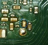
What version the picofy fw you use?For the first time with me, a device with nand skhynix did not work with the 100/100/47 ohm resistor configuration. When trying the device several times I found the error "=***" emmc int failure. Upon checking all the points, I realized that the measurements were correct. I decided to replace the 100ohm resistor on the CMD line with a 47ohm one and the problem was solved.
You are using an out of date browser. It may not display this or other websites correctly.
You should upgrade or use an alternative browser.
You should upgrade or use an alternative browser.
Staff Posts
Recent threadmarks
sharing files
Important Posts
Recent threadmarks
FirmwaresIn this case, i try 2.75 and 2.76.What version the picofy fw you use?
Why you use 100 ohm on dat0??For the first time with me, a device with nand skhynix did not work with the 100/100/47 ohm resistor configuration. When trying the device several times I found the error "=***" emmc int failure. Upon checking all the points, I realized that the measurements were correct. I decided to replace the 100ohm resistor on the CMD line with a 47ohm one and the problem was solved.
Post automatically merged:
From where did you got 2.76?? Official firmware is still 2.75In this case, i try 2.75 and 2.76.
https://github.com/rehius/usk/releases/tag/PicoFly_2.75_2023.09.09_08-16
Last edited by Myst0gan,
does this mod chip work i can only or on amazon i have a mariko switch
this is an English speaking forum, sorry
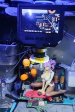
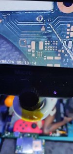
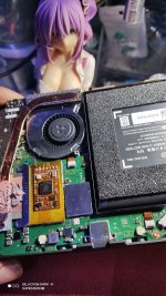
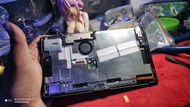
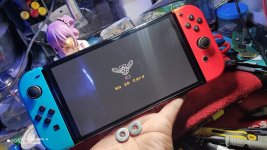
kamikaze time...i have spare time to tinker so i did what i can to do a OLED kamikaze mod ( DAT0 )....patiently diggin cleaning and hard work paid off....
Attachments
-
 412405415_871975918270300_9009590015636869865_n.jpg150.5 KB · Views: 26
 -
 412415353_871975881603637_2031124080718031352_n.jpg172.6 KB · Views: 21
 -
 411740695_871975764936982_4569283139076331287_n.jpg390.1 KB · Views: 21
 -
 412082022_871975864936972_5447307433300725215_n.jpg342.9 KB · Views: 22
 -
 412104414_871975638270328_2689438605277741329_n.jpg259.9 KB · Views: 26
kamikaze time...i have spare time to tinker so i did what i can to do a OLED kamikaze mod ( DAT0 )....patiently diggin cleaning and hard work paid off....
I just tried kamikaze again. This time patiently doing the grinding. The 0.2mm tip was good at this method. My first attemp of kamikaze was I almost cut the CMD line.
 Now I am more confident to do all these on my future OLED modding. No more removal of the board.
I just tried kamikaze again. This time patiently doing the grinding. The 0.2mm tip was good at this method. My first attemp of kamikaze was I almost cut the CMD line.Now I am more confident to do all these on my future OLED modding. No more removal of the board.
View attachment 411483
How much time would you say it takes to do the dat0 point this way? from start to finish, so to speak
- Joined
- Sep 2, 2020
- Messages
- 1,298
- Trophies
- 0
- Age
- 39
- Location
- TORONTO
- Website
- form.jotform.com
- XP
- 2,234
- Country

about 10min from grinding to solder jumper wire on the dat0How much time would you say it takes to do the dat0 point this way? from start to finish, so to speak
Hi, sorry for my English, but could someone help me, I installed the picofly chip in the OLED switch, but there are times when it causes the glitch, and there are times when it doesn't perform the glitch, so I try again, and it it works.
but when it doesn't work, it gives the sequence of yellow blinks as follows: *==.
a short one and then two long ones, and it enters the OFW.
Would anyone have any idea what it would be?
Note: EMMC value is correct
but when it doesn't work, it gives the sequence of yellow blinks as follows: *==.
a short one and then two long ones, and it enters the OFW.
Would anyone have any idea what it would be?
Note: EMMC value is correct
It is rather strange problem that I encountered two or three times. Will you try to format OFW. It worked for me when there is too much data from previous owner of the console.Hi, sorry for my English, but could someone help me, I installed the picofly chip in the OLED switch, but there are times when it causes the glitch, and there are times when it doesn't perform the glitch, so I try again, and it it works.
but when it doesn't work, it gives the sequence of yellow blinks as follows: *==.
a short one and then two long ones, and it enters the OFW.
Would anyone have any idea what it would be?
Note: EMMC value is correct
i had this one shorted once. i had to find another dead board for it. if you didn't replace it your switch would not turn on. there are no store in aliexpress selling it. the only source you can is trying to find a donor board(v1) for it.Help identify the component and its value. switch rev.1 mosfet burned out and took it with me
- Joined
- Sep 2, 2020
- Messages
- 1,298
- Trophies
- 0
- Age
- 39
- Location
- TORONTO
- Website
- form.jotform.com
- XP
- 2,234
- Country

replace dat0 resistor on rp2040 with 100 ohmHi, sorry for my English, but could someone help me, I installed the picofly chip in the OLED switch, but there are times when it causes the glitch, and there are times when it doesn't perform the glitch, so I try again, and it it works.
but when it doesn't work, it gives the sequence of yellow blinks as follows: *==.
a short one and then two long ones, and it enters the OFW.
Would anyone have any idea what it would be?
Note: EMMC value is correct
Hello just got my modded siwtch back and wondering if there is a way to transfer all of my emummc to my new switch, without having to re partition everything and back it up.
EDIT: Forgot to add this since the OLED is 64 partition would that create issues if my previous backup was based on a 32gb partition
EDIT: Forgot to add this since the OLED is 64 partition would that create issues if my previous backup was based on a 32gb partition
I'm trained to solder the mod but I need some more info that I can't find anywhere.
Hi guys, I'm training myself on soldering, and I think I can finally trained to solder the picofly it's just 4 solder I can make it with calm and some relaxing ambient sound in my ears...
But there are something that I can't find anywhere:
1. do you solder some tin on the flat that goes on the cpu, or you just advice me to put some flux and solder directly?
2. what gauge do you advice me to use for the solder wire?
3. is there any centralized website like for the 3ds/wii era where I can find anything about this mod?
4. Someone on yt advice to not cut the aluminium cover to better sit the picofly because it's needed for better airflow. is that true? Is there some video or pics that show how to place the picofly without cut the cover?
Thank you in advance to everyone would help me a bit, and wish me good luck
No need of pre-tinning, just sit the flex, apply flux and solder.1. do you solder some tin on the flat that goes on the cpu, or you just advice me to put some flux and solder directly?
36AWG for data wires, I prefer 30AWG for power (GND + 3.3V). Solder wire, just use some 63/37 SN/PB wire (edit: 0.5mm in diameter or lower is more than enough).2. what gauge do you advice me to use for the solder wire?
You're in the right place. Just read @lightninjay signature before soldering, you can find there a lot of useful info.3. is there any centralized website like for the 3ds/wii era where I can find anything about this mod?
Forget YT. For OLED and Lite there's no need to cut the shield (chip for OLED goes on the right side of SoC cover and for Lite on top of eMMC cover). For V1/V2, if you don't want to place it on top of the shield, you should cut it since there isn't much clearing space.4. Someone on yt advice to not cut the aluminium cover to better sit the picofly because it's needed for better airflow. is that true? Is there some video or pics that show how to place the picofly without cut the cover?
Ciao!
Last edited by Phantomas77,
Similar threads
- Replies
- 3
- Views
- 2K
- Replies
- 2
- Views
- 547
- Replies
- 42
- Views
- 6K
Site & Scene News
New Hot Discussed
-
-
29K views
Nintendo Switch firmware update 18.0.1 has been released
A new Nintendo Switch firmware update is here. System software version 18.0.1 has been released. This update offers the typical stability features as all other... -
22K views
Nintendo officially confirms Switch successor console, announces Nintendo Direct for next month
While rumors had been floating about rampantly as to the future plans of Nintendo, the President of the company, Shuntaro Furukawa, made a brief statement confirming... -
22K views
New static recompiler tool N64Recomp aims to seamlessly modernize N64 games
As each year passes, retro games become harder and harder to play, as the physical media begins to fall apart and becomes more difficult and expensive to obtain. The... -
21K views
TheFloW releases new PPPwn kernel exploit for PS4, works on firmware 11.00
TheFlow has done it again--a new kernel exploit has been released for PlayStation 4 consoles. This latest exploit is called PPPwn, and works on PlayStation 4 systems... -
20K views
Nintendo takes down Gmod content from Steam's Workshop
Nintendo might just as well be a law firm more than a videogame company at this point in time, since they have yet again issued their now almost trademarked usual...by ShadowOne333 128 -
16K views
Name the Switch successor: what should Nintendo call its new console?
Nintendo has officially announced that a successor to the beloved Switch console is on the horizon. As we eagerly anticipate what innovations this new device will... -
16K views
A prototype of the original "The Legend of Zelda" for NES has been found and preserved
Another video game prototype has been found and preserved, and this time, it's none other than the game that spawned an entire franchise beloved by many, the very...by ShadowOne333 32 -
14K views
Anbernic reveals specs details of pocket-sized RG28XX retro handheld
Anbernic is back with yet another retro handheld device. The upcoming RG28XX is another console sporting the quad-core H700 chip of the company's recent RG35XX 2024... -
12K views
DOOM has been ported to the retro game console in Persona 5 Royal
DOOM is well-known for being ported to basically every device with some kind of input, and that list now includes the old retro game console in Persona 5 Royal... -
12K views
Nintendo Switch Online adds two more Nintendo 64 titles to its classic library
Two classic titles join the Nintendo Switch Online Expansion Pack game lineup. Available starting April 24th will be the motorcycle racing game Extreme G and another...
-
-
-
264 replies
Name the Switch successor: what should Nintendo call its new console?
Nintendo has officially announced that a successor to the beloved Switch console is on the horizon. As we eagerly anticipate what innovations this new device will...by Costello -
230 replies
Nintendo officially confirms Switch successor console, announces Nintendo Direct for next month
While rumors had been floating about rampantly as to the future plans of Nintendo, the President of the company, Shuntaro Furukawa, made a brief statement confirming...by Chary -
128 replies
Nintendo takes down Gmod content from Steam's Workshop
Nintendo might just as well be a law firm more than a videogame company at this point in time, since they have yet again issued their now almost trademarked usual...by ShadowOne333 -
119 replies
New static recompiler tool N64Recomp aims to seamlessly modernize N64 games
As each year passes, retro games become harder and harder to play, as the physical media begins to fall apart and becomes more difficult and expensive to obtain. The...by Chary -
82 replies
Nintendo Switch firmware update 18.0.1 has been released
A new Nintendo Switch firmware update is here. System software version 18.0.1 has been released. This update offers the typical stability features as all other...by Chary -
80 replies
TheFloW releases new PPPwn kernel exploit for PS4, works on firmware 11.00
TheFlow has done it again--a new kernel exploit has been released for PlayStation 4 consoles. This latest exploit is called PPPwn, and works on PlayStation 4 systems...by Chary -
79 replies
Ubisoft reveals 'Assassin's Creed Shadows' which is set to launch later this year
Ubisoft has today officially revealed the next installment in the Assassin's Creed franchise: Assassin's Creed Shadows. This entry is set in late Sengoku-era Japan...by Prans -
78 replies
"Nintendo World Championships: NES Edition", a new NES Remix-like game, launching July 18th
After rumour got out about an upcoming NES Edition release for the famed Nintendo World Championships, Nintendo has officially unveiled the new game, titled "Nintendo...by ShadowOne333 -
71 replies
DOOM has been ported to the retro game console in Persona 5 Royal
DOOM is well-known for being ported to basically every device with some kind of input, and that list now includes the old retro game console in Persona 5 Royal...by relauby -
65 replies
Microsoft is closing down several gaming studios, including Tango Gameworks and Arkane Austin
The number of layoffs and cuts in the videogame industry sadly continue to grow, with the latest huge layoffs coming from Microsoft, due to what MIcrosoft calls a...by ShadowOne333
-
Popular threads in this forum
General chit-chat
-
 K3Nv2
Loading…
-
 @
Sicklyboy:
@SylverReZ, Oh yeah, arguably doing better than ever. They're releasing new sets constantly for it+1
@
Sicklyboy:
@SylverReZ, Oh yeah, arguably doing better than ever. They're releasing new sets constantly for it+1 -
-
-
 @
SylverReZ:
Nice. I wish they bought back collectable figurines in blind bags, which I had as a kid.
 -
 @
Sicklyboy:
I like buying the Halo Megablox blind bags every once in a while when I see them. Scratches that itch
 -
-
-
 @
hitorikuroi:
i have a question currently my atmos switch isnt picked up by pc on HOS but the cable and port do work with apx and tegra so i know the hardware is good, any clue?
 -
-
-
-
-
-
-
 @
Psionic Roshambo:
Well on a good day life does suck... lol on a bad day it just sucks differently lol+3
 -
-
-
-
-
-
 @
BakerMan:
it's just in an empty open space, like outside at night or the backrooms, depending on the branch of the hypothetical you either feel unsafe, but you actually are safe, or you feel safe, but are unsafe, also you don't actually know the truth about your safety either way
 -
-
-
-


