Hacking Hardware Picofly - a HWFLY switch modchip

Crung

Well-Known Member
Member
Joined
Jul 19, 2023
Messages
156
Trophies
0
Age
23
XP
217
Country
Romania
Couldn't the reballing have gone wrong?
well yeah sure but it worked for a couple of days,then it froze and died .for now im trying to diagnostic it.
So it looks like when testing for continuity between 1.8 v line and cmd ,with the resistor removed,i get 0 X_X Is this normal?
I measured the resistor taken from the board and it gives 4.7k so its not fryed after all?
Replaced the resistor just to be sure, still nothing.
Now instead of the picofly powering on and throwing error, the power chip for the apu gets hot :) Cool.
 
Last edited by Crung,

Makc16384

Member
Newcomer
Joined
Apr 19, 2023
Messages
24
Trophies
0
Age
39
XP
156
Country
Germany
I regularly had problems with the DAT0 contact on my OLED switch and decided to connect by drilling. Everything went well, but I spent the whole night using my wife's nail machine to do it :rofl2:

1698933065415.jpeg
 

LuigiGad

Well-Known Member
Member
Joined
May 7, 2023
Messages
167
Trophies
0
Age
56
XP
501
Country
Italy
I regularly had problems with the DAT0 contact on my OLED switch and decided to connect by drilling. Everything went well, but I spent the whole night using my wife's nail machine to do it :rofl2:

View attachment 402467
I also managed to discover the runway, but I assure you that it flies with a sneeze... It is not easy to take the point in that "well" without interrupting it
 

MichiS97

"Leftist snowflake milennial"
Member
Joined
Jun 14, 2011
Messages
1,817
Trophies
2
Age
26
Location
Munich
XP
3,630
Country
Germany
I regularly had problems with the DAT0 contact on my OLED switch and decided to connect by drilling. Everything went well, but I spent the whole night using my wife's nail machine to do it :rofl2:

View attachment 402467
This is still so amazing and crazy to me. Can you share your method of doing this? Just a rough explanation, not asking for a step by step guide :D
 

BlueBeans

Well-Known Member
Member
Joined
May 2, 2023
Messages
270
Trophies
0
Age
32
XP
270
Country
United States
do you have any pictures with the clk pad damage?
I don’t. The pad has come away from the via but was still attached to the trace.
Post automatically merged:

People has warn like thousands time in this thread, don't use grinding pen, its risky. That the only method you used, when theres no other method available.

The problem not just lays on the risk of grind that trace out of the pcb. Its also the debris, which almost couldn't be cleaned out. You will need an ultrasonic cleaner for that, and it gives another risk of destroying the component cause of the ultrasonic waves. And you need to use alcohol, if you use water, it will lead to another risk of corrotion. Even the alcohol you used have water on it, except you buy a 99% methanol/ethanol.

And even if the clk ripped, that device still could be modded, if you use emmc adapter. Since the clk, cmd, dat0, 3.3V, gnd all exist on the emmc pins.

Like i said, the clk point is risky. I rather use emmc adapter, to solve the risky clk, the problematic dat0, and the difficulty of cmd point, in one solution.
Thank you for all the info. I didn’t know you could use an emmc adapter for those other points. How would one go about that? Obviously I would still like to mod it but u didn’t want to disturb my hard work getting it back up and running. It’s my personal switch. Would have never risked a customers switch trying something new.
 

Vigintiduo

Well-Known Member
Newcomer
Joined
Sep 13, 2023
Messages
63
Trophies
0
Age
33
XP
189
Country
Italy
Un

Always in the same place, I go slowly completing each layer and cleaning to be able to see, a drop of liquid flux to hydrate and to be able to see through the layers. I scratch the line just enough with a pin and reveal it. Green nask around, flux, tin, I connected an enameled wire and secured it with hreen mask, first the hole and then the run. A slight tug tears off the line.

Yesterday doing internships I managed to change a SKhynix nand for a Samsung and restore the backup, take the opportunity to put enameled wire and get a permanent line.
I'm probably lacking the knowledge but did you solder the dat0 wire as a jumper to that via? So that you could get an easy solder point from that pad on the right
 

AceCuba

Well-Known Member
Newcomer
Joined
Feb 4, 2021
Messages
79
Trophies
0
Age
25
Location
Mi cueva
XP
300
Country
Cuba
hey guys some help here , i got a rp2040 zero , that works only if you press the rest on the pico , when the console starts the pico do nothing , no led and the console goes to ofw . when you power down the console pres reset on the pico and then pres power on the console everything works like a charm . any ideas
 

jkyoho

Well-Known Member
Member
Joined
Sep 2, 2020
Messages
1,320
Trophies
0
Age
39
Location
TORONTO
Website
form.jotform.com
XP
2,259
Country
Canada
hey guys some help here , i got a rp2040 zero , that works only if you press the rest on the pico , when the console starts the pico do nothing , no led and the console goes to ofw . when you power down the console pres reset on the pico and then pres power on the console everything works like a charm . any ideas
i2c undervoltage hack
If your glitch is unstable (==* error), and the proper boot happens only when you press Reset after joycon logo, you can add two more wires to make glitch much better.”
 

AceCuba

Well-Known Member
Newcomer
Joined
Feb 4, 2021
Messages
79
Trophies
0
Age
25
Location
Mi cueva
XP
300
Country
Cuba
my glich is stable , the pico is the one that when you put the 3.3v line she does nothing until you hit that rest bottom
Post automatically merged:

my glich is stable , the pico is the one that when you put the 3.3v line she does nothing until you hit that rest bottom
i never got any error code , the pico is like no led no anything until you hit the reset boton on the pico with the console off
 

deeps

Well-Known Member
Member
Joined
Jul 3, 2007
Messages
454
Trophies
1
XP
1,277
Country
Does anyone have a link to this chip? I can’t seem to find it.

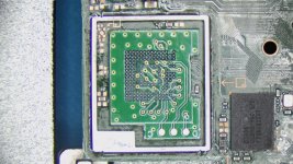
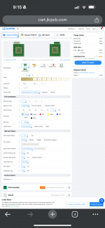
This adapter is no longer sold by any seller on aliexpress, However you can order your own by ordering from JLCPCB with the files from the link provided by @Crung above. You will need to reball the adapter and the emmc.
 

MichiS97

"Leftist snowflake milennial"
Member
Joined
Jun 14, 2011
Messages
1,817
Trophies
2
Age
26
Location
Munich
XP
3,630
Country
Germany
This adapter is no longer sold by any seller on aliexpress, However you can order your own by ordering from JLCPCB with the files from the link provided by @Crung above. You will need to reball the adapter and the emmc.
What's the best way to install these btw? Reball adapter => solder to pcb => reball emmc => solder to adapter

Or

Reball emmc => reball adapter => solder emmc to adapter => solder emmc+adapter to PCB?
 

deeps

Well-Known Member
Member
Joined
Jul 3, 2007
Messages
454
Trophies
1
XP
1,277
Country
What's the best way to install these btw? Reball adapter => solder to pcb => reball emmc => solder to adapter

Or

Reball emmc => reball adapter => solder emmc to adapter => solder emmc+adapter to PCB?

I'm doing adapter first, then emmc. Seems more logical, and it's a good idea to not expose the emmc to more heat than necessary. So the workflow is as follows:

- detach emmc from mainboard
- clean mainboard with solder wick
- clean emmc with solder wick
- reball emmc
- reball adapter (on the bottom side)
- attach adapter to mainboard
- attach emmc to adapter
 
  • Like
Reactions: LogicalMadness

Crung

Well-Known Member
Member
Joined
Jul 19, 2023
Messages
156
Trophies
0
Age
23
XP
217
Country
Romania
What's the best way to install these btw? Reball adapter => solder to pcb => reball emmc => solder to adapter

Or

Reball emmc => reball adapter => solder emmc to adapter => solder emmc+adapter to PCB?
im pretty sure you solder the adapter to the motherboard and then the emmc to the adapter. if you solder the emmc to adapter first and then to motherboard im pretty sure you wont have enough heat or no way of knowing if its properly there
 

BlueBeans

Well-Known Member
Member
Joined
May 2, 2023
Messages
270
Trophies
0
Age
32
XP
270
Country
United States

Attachments

  • IMG_0281.png
    IMG_0281.png
    429.2 KB · Views: 17
Last edited by BlueBeans,

Crung

Well-Known Member
Member
Joined
Jul 19, 2023
Messages
156
Trophies
0
Age
23
XP
217
Country
Romania
Great. Thank you! Do you know how many layers the board is? I’m assuming at least 2 right?
Post automatically merged:

I’ve never done this before. Does anything need to change?
me neither,im also new to it and will order soon. i dont think you need to do any settings? pretty sure everything is in gerber files and it loads automatically. Right @abal1000x ?
 

Site & Scene News

Popular threads in this forum

General chit-chat
Help Users
  • No one is chatting at the moment.
    K3Nv2 @ K3Nv2: https://youtu.be/q1474nWP0bI?si=5v445vycfskxD3V8