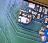
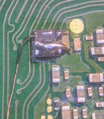
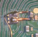
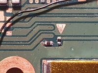
I've been doing a single mosfet on the back ever since it came out. Works great. I like to think the issue is almost always not enough solder. I'm always generous with the amounts on D and S. Maybe some pics? Here's a fast-glitching install:Well, probably it's just me, but in 3 different consoles that I tried, I never got them to work with a single MOSFET (IRFHS8342 from Digikey, 0.31mm wires on S&D, 100/100/47 and 47/47/47 config, RP2040-zero FW2.73):
- OLED soldered to CPU cap --> ==* (CPU always reach BCT check (no glitch reaction, check mosfet)
- OLED soldered in the back (deeps and Abal points) --> ==*
- Erista unpatched soldered in the back (Abal's points) --> glitched few times and than ==*
Some thoughts that came into my mind:
Would like to hear your thoughts on this
- should I add another MOSFET so the current will be higher?
- since the back points are more distant to the SoC than the "original" caps, is the distance enough to affect the glitch?
- should I stick to double MOSFET on SoC caps as usual? Probably I will.
- what am I missing here?

You are using an out of date browser. It may not display this or other websites correctly.
You should upgrade or use an alternative browser.
You should upgrade or use an alternative browser.
Staff Posts
Recent threadmarks
sharing files
Important Posts
Recent threadmarks
FirmwaresThat's the sh*ttiest DAT0 ("OATO" as they mispelled it) adaptor ever, probably it's shorting some other eMMC solder joint or is not making a good contact. Take it out and change it for something else (the black one is better in my opinion). THE BEST solution still remains a nice reball with a direct wire, if you have a possibility, I highly advice you to do it.My pico in oled shows =*== error - emmc test faliure, read failed. Console boots to normal os.
My diode mode values looks like below
0.614 dat0
0.68 cmd
0.73 clk
1.5 rst
0,62 cpu
Every connnection and every resistor looks ok. Emmc adapter looks like on the photo. Where can I look for the problem?
Another thing, have you needed to jump for the correct color code? If so what points, on the tiny? Just had to download an older guide to see what colors meant whatNope doesn't have it. I bought real ones from the same store, but when I reordered more these were those ones with the big connector.
That sounds good. I'll give that a try for my next install. Thanks
Even if my diode mode value is ok?That's the sh*ttiest DAT0 ("OATO" as they mispelled it) adaptor ever, probably it's shorting some other eMMC solder joint or is not making a good contact. Take it out and change it for something else (the black one is better in my opinion). THE BEST solution still remains a nice reball with a direct wire, if you have a possibility, I highly advice you to do it.
Happened to me few times in the past when I was using adapters, ok diode reading but still not good enough contact.Even if my diode mode value is ok?
At least it is not bridging the wrong eMMC ball in your case, since your console boots to OFW. Of course one cannot be sure that it is DAT0 without analysing the console, but I would start from there.
Those OATO adapters were discussed in this thread in the past, here's an example.
Post automatically merged:
I used wires, will throw a pic later.I've been doing a single mosfet on the back ever since it came out. Works great. I like to think the issue is almost always not enough solder. I'm always generous with the amounts on D and S. Maybe some pics? Here's a fast-glitching install:
Hello, friends.
For those who do EMMC reball, which material do u use for the reball?
Solder paste or welding spheres? And what mm du u use?
For those who do EMMC reball, which material do u use for the reball?
Solder paste or welding spheres? And what mm du u use?
- Joined
- Sep 2, 2020
- Messages
- 1,320
- Trophies
- 0
- Age
- 39
- Location
- TORONTO
- Website
- form.jotform.com
- XP
- 2,259
- Country

paste or 0.3mm ballsHello, friends.
For those who do EMMC reball, which material do u use for the reball?
Solder paste or welding spheres? And what mm du u use?
Hello, friends.
For those who do EMMC reball, which material do u use for the reball?
Solder paste or welding spheres? And what mm du u use?
I use paste. Takes a bit of training to get right but it's quick and easy once you get the hang of it
Thank for Your support.Search in this thread, @lightninjay told some recomendation. And i had confirmed its works in seconds (between 15-50s) under transparent uv resin.
https://gbatemp.net/threads/picofly-a-hwfly-switch-modchip.622701/post-10193981
Which power do I choose?
Is there a need for a power supply not supplied?
I had seen something for dental practices, would the UV ray be more concentrated?
IT'S cordless, with batter, rechargeable, more power.
See here
https://a.aliexpress.com/_m05QpjU
I confirmed the 20mW version. Higher powered should be better, just becareful.Thank for Your support.
Which power do I choose?
Is there a need for a power supply not supplied?
If i focused it on airbag, it smoked (melt the rubber airbag), so becareful on handling it. Its definitely not a toy.
Yes it need external power supply. I've bought cheap usb to 2.5mm female jack cable converter for this reason.
Track from the previous link you will get into logicalmadness post, about the link lightninjay used on the 5mW powered battery laser pointer, if you want battery version.
The light spec looks the same 400nm, seems it doesn't have focus knob, like the previous product. Without the focuser, i am not conviced that this could be effective. You might bought it, and share the result.I had seen something for dental practices, would the UV ray be more concentrated?
IT'S cordless, with batter, rechargeable, more power.
See here
https://a.aliexpress.com/_m05QpjU
I've use this laser + uv resin for lot of purposes. Its super usefull. I fix some cmos battery holder using this uv resin. And glue something using this too. I also glued some air sealed pillow which have punctures, using the combination of special glue and this laser. In conclusion this device is worth every penny you spent on.
Last edited by abal1000x,
Having a curved tip, concentrated light beam emission (at a short distance, being used for the teeth) I would say it could be safer and more comfortable (includes battery).I confirmed the 20mW version. Higher powered should be better, just becareful.
If i focused it on airbag, it smoked (melt the rubber airbag), so becareful on handling it. Its definitely not a toy.
Yes it need external power supply. I've bought cheap usb to 2.5mm female jack cable converter for this reason.
Track from the previous link you will get into logicalmadness post, about the link lightninjay used on the 5mW powered battery laser pointer, if you want battery version.
The light spec looks the same 400nm, seems it doesn't have focus knob, like the previous product. Without the focuser, i am not conviced that this could be effective. You might bought it, and share the result.
I've use this laser + uv resin for lot of purposes. Its super usefull. I fix some cmos battery holder using this uv resin. And glue something using this too. I also glued some air sealed pillow which have punctures, using the combination of special glue and this laser. In conclusion this device is worth every penny you spent on.
I purchased it out of curiosity.
I'll update you shortly.
I see that many are asking for info on reball.
I made a video with the microscope camera, if it helps, I'll put it on YouTube with the various tips that my humble experience has allowed me to learn.
Post automatically merged:
OT:
I got carried away, I started buying on Aliexpress and I bought spare parts and equipment of all kinds, even a new soldering station, which is the same one I already have, just an updated version, which I don't need :- )
END OF OT
I attach a screen of the lamp I purchased, specifications 2200mw/cm2, it talks about hardening in 1 second (with dental resins obviously), we will see how it behaves with the maskuv (it would be useful if it worked in 10 seconds, a lot of time saved).
Attachments
Last edited by cicci084,
My pico in oled shows =*== error - emmc test faliure, read failed. Console boots to normal os.
My diode mode values looks like below
0.614 dat0
0.68 cmd
0.73 clk
1.5 rst
0,62 cpu
Every connnection and every resistor looks ok. Emmc adapter looks like on the photo. Where can I look for the problem?
Yes, it happened to me in both CLK and Dat0. Readings ok but boots to OFW. That's always an installer issue. I no longer do Dat0 adaptors because it's a hit-and-miss at this point. Even good Aliexpress vendors would later ship shitty adaptors. Nothing beats a good reball, be a reballer!Even if my diode mode value is ok?
tl,dr: apparently succesful OLED install suddenly turn into blue screen
Hi guys. I'm having quite the misfortune now with a OLED Switch.
Yesterday I installed the mod while also following a bit of sthetix's last video for oleds and had all done, with nice diode readings.
The Switch was working, booting into hekate and syscfw as well. I play a bit just to test it and turn it off.
I suddenly remember I wanted to check something and try to turn it on again, only to be greeted by OFW and the blinking error for missing D0 connection. I tell myself that I'll deal with that the next day.
Buuuut, the next day it's apparently working again. Of course I'm not trusting this, so I just boot into hekate to get an emmc backup which completes without any error. However, shortly after, Hekate tells me to reboot Nyx, which I do. The console reboots to hekate but now I'm seeing green artifacts all over the screen. I turn off the console and try to desolder everything from the chip.
Now I'm getting the infamous Blue Screen. Can't boot to recovery or anything. Tried soldering the chip back on and I get a succesful LED sequence but the screen is black. If I remove the SD card instead, I get the usual "NO SD" message.
Tried removing the DAT0 adapter (I used the friction method as suggested in the last video from sthetix) but I still get a blue screen.
Any idea of what I can do for it now?
On the oled switch, the dat0 point can be taken from the emmc board? do i need to have this flex dat0?
View attachment 360242
@abal1000x
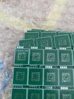
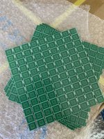
They came in today, I am curious to see how will they perform.
By the way these are 0.6mm thick pcbs.
They came in today, I am curious to see how will they perform.
By the way these are 0.6mm thick pcbs.
Attachments
So I moved it from before to after (Erista install) and it glitches fast, same MOSFET. Looks like it was a connection issue, so thanks for your help.I've been doing a single mosfet on the back ever since it came out. Works great. I like to think the issue is almost always not enough solder. I'm always generous with the amounts on D and S. Maybe some pics? Here's a fast-glitching install:
Still I'm a bit perplexed, since the wires were short and large enough to handle the current (0.31mm). The important thing is that it works fine now
Attachments
LOL, want to see it performs : ordered in hundreds.. Like a boss.. Hahaha@abal1000x
They came in today, I am curious to see how will they perform.
By the way these are 0.6mm thick pcbs.

It is dirt cheap this wayLOL, want to see it performs : ordered in hundreds.. Like a boss.. Hahaha
Hey all. Hope you're all well. I have posted this a few days ago on the AIO thread and have updated my findings but here because I wanted some input atleast. So freinds oled switch modded a month ago. Working fine. He left it on dock overnight. Morning he found it was hot and turned it on. It went into emmc but then died. and the cmd error code flashed when trying to turn it on again. So black screen and cmd code.
He gave it to me and I found a short on both ends of the cmd resitor and one end of the 47k resistor next to it. So i replaced the 4.7kR first. That didn't fix the issue so I did some research and found that reflowing the emmc would fix it. Did that and that fixed the picomod as it glitched successfully again but there was still no picture (black screen). The 4.7k R was now giving correct resistance values and not showing shorts. The short on the 47kR was still there so I went to replace that resistor. When taking off the resistor I double checked the empty pads of the resistor and there was a short still on the pad!? Replaced the resistors anyway and still have a short and no correct Resistance values either.
I have racked my brain around it but im getting no where. I removed the mosfet and even the emmc to completely rule out them as possible variables. Still getting that short. Followed some lines to that Resistor point to some nearby caps and the audio chip and they all are fine. So it does not boot into Anything. No OFW nothing. but it did finally glitch right. Weird.
Anyone have any ideas? Thanks
Attachments
Similar threads
- Replies
- 5
- Views
- 2K
- Replies
- 2
- Views
- 720
- Replies
- 42
- Views
- 7K
Site & Scene News
New Hot Discussed
-
-
34K views
New static recompiler tool N64Recomp aims to seamlessly modernize N64 games
As each year passes, retro games become harder and harder to play, as the physical media begins to fall apart and becomes more difficult and expensive to obtain. The... -
28K views
Nintendo officially confirms Switch successor console, announces Nintendo Direct for next month
While rumors had been floating about rampantly as to the future plans of Nintendo, the President of the company, Shuntaro Furukawa, made a brief statement confirming... -
26K views
Name the Switch successor: what should Nintendo call its new console?
Nintendo has officially announced that a successor to the beloved Switch console is on the horizon. As we eagerly anticipate what innovations this new device will... -
15K views
DOOM has been ported to the retro game console in Persona 5 Royal
DOOM is well-known for being ported to basically every device with some kind of input, and that list now includes the old retro game console in Persona 5 Royal... -
14K views
Mario Builder 64 is the N64's answer to Super Mario Maker
With the vast success of Super Mario Maker and its Switch sequel Super Mario Maker 2, Nintendo fans have long been calling for "Maker" titles for other iconic genres... -
13K views
Anbernic reveals the RG35XXSP, a GBA SP-inspired retro handheld
Retro handheld manufacturer Anbernic has revealed its first clamshell device: the Anbernic RG35XXSP. As the suffix indicates, this handheld's design is inspired by... -
12K views
Majora’s Mask PC port 2Ship2Harkinian gets its first release
After several months of work, the Harbour Masters 64 team have released their first public build of 2Ship2Harkinian, a feature-rich Majora's Mask PC port. This comes... -
12K views
"Nintendo World Championships: NES Edition", a new NES Remix-like game, launching July 18th
After rumour got out about an upcoming NES Edition release for the famed Nintendo World Championships, Nintendo has officially unveiled the new game, titled "Nintendo...by ShadowOne333 78 -
12K views
Microsoft is closing down several gaming studios, including Tango Gameworks and Arkane Austin
The number of layoffs and cuts in the videogame industry sadly continue to grow, with the latest huge layoffs coming from Microsoft, due to what MIcrosoft calls a...by ShadowOne333 65 -
11K views
Ubisoft reveals 'Assassin's Creed Shadows' which is set to launch later this year
Ubisoft has today officially revealed the next installment in the Assassin's Creed franchise: Assassin's Creed Shadows. This entry is set in late Sengoku-era Japan...
-
-
-
321 replies
Name the Switch successor: what should Nintendo call its new console?
Nintendo has officially announced that a successor to the beloved Switch console is on the horizon. As we eagerly anticipate what innovations this new device will...by Costello -
233 replies
Nintendo officially confirms Switch successor console, announces Nintendo Direct for next month
While rumors had been floating about rampantly as to the future plans of Nintendo, the President of the company, Shuntaro Furukawa, made a brief statement confirming...by Chary -
141 replies
New static recompiler tool N64Recomp aims to seamlessly modernize N64 games
As each year passes, retro games become harder and harder to play, as the physical media begins to fall apart and becomes more difficult and expensive to obtain. The...by Chary -
96 replies
Ubisoft reveals 'Assassin's Creed Shadows' which is set to launch later this year
Ubisoft has today officially revealed the next installment in the Assassin's Creed franchise: Assassin's Creed Shadows. This entry is set in late Sengoku-era Japan...by Prans -
94 replies
Majora’s Mask PC port 2Ship2Harkinian gets its first release
After several months of work, the Harbour Masters 64 team have released their first public build of 2Ship2Harkinian, a feature-rich Majora's Mask PC port. This comes...by Scarlet -
88 replies
The Kingdom Hearts games are coming to Steam
After a little more than three years of exclusivity with the Epic Games Store, Square Enix has decided to bring their beloved Kingdom Hearts franchise to Steam. The...by Chary -
78 replies
"Nintendo World Championships: NES Edition", a new NES Remix-like game, launching July 18th
After rumour got out about an upcoming NES Edition release for the famed Nintendo World Championships, Nintendo has officially unveiled the new game, titled "Nintendo...by ShadowOne333 -
71 replies
DOOM has been ported to the retro game console in Persona 5 Royal
DOOM is well-known for being ported to basically every device with some kind of input, and that list now includes the old retro game console in Persona 5 Royal...by relauby -
65 replies
Microsoft is closing down several gaming studios, including Tango Gameworks and Arkane Austin
The number of layoffs and cuts in the videogame industry sadly continue to grow, with the latest huge layoffs coming from Microsoft, due to what MIcrosoft calls a...by ShadowOne333 -
64 replies
Select PlayStation 2 games are coming to PlayStation 5
Sony is once more attempting to reintroduce players to their older library of games by re-releasing classic PlayStation 2 titles onto the PlayStation Store. During...by Chary
-
Popular threads in this forum
General chit-chat
-
 Veho
Loading…
 -
 Psionic Roshambo
Loading…
-
-
-
-
-
-
-
-
 @
BakerMan:
truth be told, i agree with psi, i dislike both candidates, but i'd probably vote trump simply because the economy was better during his presidency+1
 -
 @
AngryCinnabon:
Just be careful, if trump ends up winning and using project 2025 America might really change...for the worse.
 -
-
 @
AngryCinnabon:
anything that offers trump an opportunity to become an actual dictator
is bad in my book, i could care less if it wasn't for that... -
-
-
-
-
 @
Psionic Roshambo:
@BakerMan, yeah that's about the only reason I would vote for Trump over Biden.+1
@
Psionic Roshambo:
@BakerMan, yeah that's about the only reason I would vote for Trump over Biden.+1 -
-
-
 @
Veho:
I don't give a fuck about what happens to America but I would like it if your shit didn't spill out on the rest of the world, thank you.+3
 -
-
 @
AncientBoi:
I give a fuck about what happens to America but I would like it if our shit didn't spill out on the rest of the world, thank you.+2
 -
-
 @
Psionic Roshambo:
@Veho, didn't need any news. Just going to the store and buying groceries is a constant reminder.
@
Psionic Roshambo:
@Veho, didn't need any news. Just going to the store and buying groceries is a constant reminder. -
-

