Hacking Hardware Picofly - a HWFLY switch modchip

Minkaxy

Active Member
Newcomer
Joined
Nov 19, 2018
Messages
43
Trophies
0
Age
40
XP
547
Country
Thailand
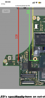
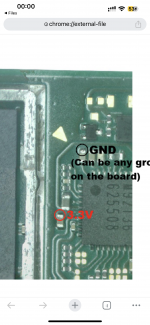
Seems like you source the 3.3v from a wrong point.
Thank for answer

In oled i use this point same as the picture in attachment.

V1,v2 too
Post automatically merged:

- You should use 38-40awg, no need to use thicker wire.
- 47ohm and 100ohm, no 1000ohm (maybe it was a typo).
- Most of the dat0 are shit, so if you are not sure you got the right one this can be the main issue for most of the things.
- Flex is hit and miss at this point, you are better using bare mosfet.
Add to this flux residue, cold joints, posible shorts after shield placement, possible wrong sourcing of 3v3 and gnd (especially on Lite) and you got yourself the recepie for 99% of the issues you described.
Lets see after you upload pictures...
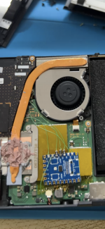
This is what i found on my phone but tomorrow I will take a new pic. And upload again.
 

Attachments

  • IMG_9660.png
    IMG_9660.png
    5.6 MB · Views: 50
  • IMG_9661.png
    IMG_9661.png
    8 MB · Views: 47
  • IMG_9662.png
    IMG_9662.png
    8.7 MB · Views: 49
Last edited by Minkaxy,

abal1000x

Well-Known Member
Member
Joined
Jun 5, 2022
Messages
1,063
Trophies
0
XP
1,374
Country
Gaza Strip
Thank for answer

In oled i use this point same as the picture in attachment.

V1,v2 too
Thats correct.

Another 3.3v alt on v1
Screen Shot 2023-09-04 at 00.13.40.png

Post automatically merged:

Thank for answer

In oled i use this point same as the picture in attachment.

V1,v2 too
Post automatically merged:


This is what i found on my phone but tomorrow I will take a new pic. And upload again.
You might try this firmware to emmc init failure, after successfull glitch.
i change slightly the version to differentiate, v200.74.
Use it on your own risk. I am not responsible.
I might push the code to my github today, if you want to read it.
The change is i fixed the part when the rp2040 'shutdown' after the light code.
 

Attachments

  • firmware.uf2.zip
    243.5 KB · Views: 18
  • update.bin.zip
    57.7 KB · Views: 15
Last edited by abal1000x,
  • Like
Reactions: LuigiGad

QuiTim

Well-Known Member
Member
Joined
Mar 30, 2023
Messages
756
Trophies
0
XP
1,162
Country
Albania
Thank for answer

In oled i use this point same as the picture in attachment.

V1,v2 too
Post automatically merged:


This is what i found on my phone but tomorrow I will take a new pic. And upload again.
These look good. The 3v3 point issue is mainly on Lite models
 

Minkaxy

Active Member
Newcomer
Joined
Nov 19, 2018
Messages
43
Trophies
0
Age
40
XP
547
Country
Thailand
Thats correct.

Another 3.3v alt on v1
View attachment 391888
Post automatically merged:


You might try this firmware to emmc init failure, after successfull glitch.
i change slightly the version to differentiate, v200.74.
Use it on your own risk. I am not responsible.
I might push the code to my github today, if you want to read it.
The change is i fixed the part when the rp2040 'shutdown' after the light code.
Thank you. I will try that I found sometime after turn off the nintendo switch rp2040 try to glitch and after successful glitch then nothing happened. Maybe your fw can help.

The emmc init failure that I found, I found shorted on the cap around emmc and I reball emmc and it fixed the issued.

I don’t know what is the cause to make it gone bad.

Try several things past 3 month and doesn’t seem to found out.
Post automatically merged:

Yes thats already correct.

The 47ohms on Dat0 might throws emmc slow mode on v1.
Yes it is an old pic before you suggest to use 100 ohm resistor but every solder point is kinda same.
 

abal1000x

Well-Known Member
Member
Joined
Jun 5, 2022
Messages
1,063
Trophies
0
XP
1,374
Country
Gaza Strip
Thank you. I will try that I found sometime after turn off the nintendo switch rp2040 try to glitch and after successful glitch then nothing happened. Maybe your fw can help.

The emmc init failure that I found, I found shorted on the cap around emmc and I reball emmc and it fixed the issued.

I don’t know what is the cause to make it gone bad.

Try several things past 3 month and doesn’t seem to found out.
Thats firmware is for scenario:
When you successfull glitch and goes to hekate, then get the slow emmc problem, even though already put the 100 ohms on the dat0 and/or cmd.

The cause is because the rp2040 doesn't sleep (lowering the voltage, stopping the clock, etc).
Thats made the cmds/dat0 line interfered the communication between cpu and the emmc.
The best solution of course to turn off completely the rp2040 after successful glitch.
So the line is in high impedance, so its not interfering the communication.
 

Minkaxy

Active Member
Newcomer
Joined
Nov 19, 2018
Messages
43
Trophies
0
Age
40
XP
547
Country
Thailand
These look good. The 3v3 point issue is mainly on Lite models
yep, I done the blue screen on lite model several day ago and don’t seem what cause it but I suggest that my hand shake when solder the 3.3 point and maybe the cap gone bad or something
Post automatically merged:

Thats firmware is for scenario:
When you successfull glitch and goes to hekate, then get the slow emmc problem, even though already put the 100 ohms on the dat0 and/or cmd.

The cause is because the rp2040 doesn't sleep (lowering the voltage, stopping the clock, etc).
Thats made the cmds/dat0 line interfered the communication between cpu and the emmc.
The best solution of course to turn off completely the rp2040 after successful glitch.
So the line is in high impedance, so its not interfering the communication.
And do you think it can cause the heat to make cpu or emmc to be broken.

Because most of the issued that I found is fixed by reflow the cpu.
 

Tom8823

Well-Known Member
Newcomer
Joined
Jun 22, 2020
Messages
54
Trophies
0
Age
36
XP
500
Country
Canada
Sorry if this has been discussed before but I installed my chip couple of months ago and I probably have old firmware on it but something weird happened to me today.

1. My switch was in sleep mode for couple of days until the battery was completely drained
2. I connected the charger and switch woke up to Hekate on itself upon connecting cable
3. While the charger was still connected I hit power off in hekate.
4. Switch was charging almost whole day and then without waking it up and checking battery level I assumed it has to be already 100% and I disconnected it from charger for the night.
5. Today I tried to turn it on, no reaction to power button
6. I panicked and connected charger, still no reaction to cable and power button.
7. Finally I held power button for 10 seconds and pressed power button shortly again to which switch finally turned on but battery level was only at 62%

What happened? Was this old firmware bug or something? Has this been ever identified? Sorry but since I installed my chip there is at least 200 more pages in this topic and asking will be faster

EDIT: Just checked, my firmware is at 2.67
 

Minkaxy

Active Member
Newcomer
Joined
Nov 19, 2018
Messages
43
Trophies
0
Age
40
XP
547
Country
Thailand
These look good. The 3v3 point issue is mainly on Lite models
IMG_9667.jpeg


This is oled installed :)
I think the solder point is correct.
3.3v is on the correct point.
But the issued I mention before still occur on many device that I installed rp2040.
Even instinct-nx I found the issued same.
Post automatically merged:

Sorry if this has been discussed before but I installed my chip couple of months ago and I probably have old firmware on it but something weird happened to me today.

1. My switch was in sleep mode for couple of days until the battery was completely drained
2. I connected the charger and switch woke up to Hekate on itself upon connecting cable
3. While the charger was still connected I hit power off in hekate.
4. Switch was charging almost whole day and then without waking it up and checking battery level I assumed it has to be already 100% and I disconnected it from charger for the night.
5. Today I tried to turn it on, no reaction to power button
6. I panicked and connected charger, still no reaction to cable and power button.
7. Finally I held power button for 10 seconds and pressed power button shortly again to which switch finally turned on but battery level was only at 62%

What happened? Was this old firmware bug or something? Has this been ever identified? Sorry but since I installed my chip there is at least 200 more pages in this topic and asking will be faster

EDIT: Just checked, my firmware is at 2.67
It happened to me many time I don’t know how maybe the switch itself wakes up and got stuck at black screen then it drained the battery.

Have to force shutdown and turn it on again.
 

abal1000x

Well-Known Member
Member
Joined
Jun 5, 2022
Messages
1,063
Trophies
0
XP
1,374
Country
Gaza Strip
yep, I done the blue screen on lite model several day ago and don’t seem what cause it but I suggest that my hand shake when solder the 3.3 point and maybe the cap gone bad or something
Post automatically merged:


And do you think it can cause the heat to make cpu or emmc to be broken.

Because most of the issued that I found is fixed by reflow the cpu.
The reflow cpu might because you mod the mosfet on the cpu.

I myself choose the safer one which is in the back pcb.
 

Minkaxy

Active Member
Newcomer
Joined
Nov 19, 2018
Messages
43
Trophies
0
Age
40
XP
547
Country
Thailand
The reflow cpu might because you mod the mosfet on the cpu.

I myself choose the safer one which is in the back pcb.
I will try the point on the back too.

This switch v1 I installed rp2040 three days ago everything works fine after first try then sleep and today cannot turn it on. Led says bad cpu or poor wiring.

I don’t know what went wrong now. Can you suggest anything on this motherboard.
IMG_9677.jpeg

IMG_9678.jpeg
 

abal1000x

Well-Known Member
Member
Joined
Jun 5, 2022
Messages
1,063
Trophies
0
XP
1,374
Country
Gaza Strip
I will try the point on the back too.

This switch v1 I installed rp2040 three days ago everything works fine after first try then sleep and today cannot turn it on. Led says bad cpu or poor wiring.

I don’t know what went wrong now. Can you suggest anything on this motherboard. View attachment 391972
The soldering looks good.
My cheap guess is the soldering on the mosfet not solid, hence the error (bad cpu / poor wiring). The firmware not detecting any glitch at all.


Out of topic:
I think this point is the safest one, since its big pad, so the soldering will be solid, and easy.
photo_6316818778771535392_y.jpg


And the mosfet on the back pcb, easy to solder and less risky.
photo_6316818778771535394_y.jpg

Post automatically merged:

I will try the point on the back too.

This switch v1 I installed rp2040 three days ago everything works fine after first try then sleep and today cannot turn it on. Led says bad cpu or poor wiring.

I don’t know what went wrong now. Can you suggest anything on this motherboard. View attachment 391972
View attachment 391973
I just know that you update the picture with the mosfet.
You need to add kapton tape to that big blob of solder on the cap.
It might bridge with the cpu case.
 
Last edited by abal1000x,

Minkaxy

Active Member
Newcomer
Joined
Nov 19, 2018
Messages
43
Trophies
0
Age
40
XP
547
Country
Thailand
The soldering looks good.
My cheap guess is the soldering on the mosfet not solid, hence the error (bad cpu / poor wiring). The firmware not detecting any glitch at all.


Out of topic:
I think this point is the safest one, since its big pad, so the soldering will be solid, and easy.
View attachment 391974

And the mosfet on the back pcb, easy to solder and less risky.
View attachment 391976
Thank for reply. then I should switch to use the mosfet and see If it solve the problem.
suspect the flex cable is a bad guy in my case.
 

abal1000x

Well-Known Member
Member
Joined
Jun 5, 2022
Messages
1,063
Trophies
0
XP
1,374
Country
Gaza Strip
Thank for reply. then I should switch to use the mosfet and see If it solve the problem.
suspect the flex cable is a bad guy in my case.
That big blob of solder might bridging with the cpu case.
Try to turn it on like that or add kapton tape before closing the cpu case.
 

abal1000x

Well-Known Member
Member
Joined
Jun 5, 2022
Messages
1,063
Trophies
0
XP
1,374
Country
Gaza Strip
Same,

reflow the cpu and everything back to normal now.
Thats weird.
I've already assume that our behaviour is different each other.
Like chef, every of us has their own way to solder.

I've suspect that someone might solder it hot enough to melt the bga pin under it.


What is the temperature you use when solder the cap, and in average how long you heat the solder.

For me usually 350 degrees Celsius, and the touch usually i limit it to 3s maxed 5s.
 
  • Like
Reactions: snaker

Minkaxy

Active Member
Newcomer
Joined
Nov 19, 2018
Messages
43
Trophies
0
Age
40
XP
547
Country
Thailand
Same,

reflow the cpu and everything back to normal now.

Thats weird.
I've already assume that our behaviour is different each other.
Like chef, every of us has their own way to solder.

I've suspect that someone might solder it hot enough to melt the bga pin under it.


What is the temperature you use when solder the cap, and in average how long you heat the solder.

For me usually 350 degrees Celsius, and the touch usually i limit it to 3s maxed 5s.
300 degrees and 3s to 5s same.

I used to installed with sx, hwfly before and all of it work fine.
but after the instinct-nx chip came out and I try it, this issued happen.
and now I switch to use rp2040 the issued is still happen.

so I doubt maybe myself did something wrong but I don't know, try to inspect myself and every solder point and try another tools, wire. the problem still the same.

Maybe the solder point on the cpu bridge with the plate, I will try to add kapton tape there.
 
  • Like
Reactions: raksmey1231

Site & Scene News

Popular threads in this forum

General chit-chat
Help Users
    Sonic Angel Knight @ Sonic Angel Knight: @_@