Ok. Thank you. Will order now.i would go with th equivalent of 0,2 since 34 is 0.15 i think
You are using an out of date browser. It may not display this or other websites correctly.
You should upgrade or use an alternative browser.
You should upgrade or use an alternative browser.
Staff Posts
Recent threadmarks
sharing files
Important Posts
Recent threadmarks
FirmwaresBro, post 10,023 of this thread should not be someone answering what kind of wire is needed for mosfet install. As Dee87 said, this has been answered so many times even my grandkids are gonna hear stories of what wire was used in the famous PicoFly mod for switch.Or should I get 32awg? Since that’s the 0.2 equivalent
The 0.2mm is standard. You can use thinner, but it can burn, damage switch or god knows what. You can use thicker but it's harder to work with.
Edit: just so we are clear, thinner wire can be used but you need to solder SDA/SCL wires aswell so the voltage is lowered by pico (read Rehius post about it). Only do this if you know what you are doing.
Last edited by QuiTim,
So what would you suggest for the remaining wire? I ordered 36awg insulated a few days ago that should be here next week. Is that ok?i would go with th equivalent of 0,2 since 34 is 0.15 i think
- Joined
- Jul 12, 2010
- Messages
- 162
- Trophies
- 1
- Age
- 36
- Location
- Bananna Land.
- Website
- www.nerdfy.com.br
- XP
- 843
- Country

Purely trauma!why do u think a reballing the emmc would help ? have u ever put heat on the emmc so have u reflowed it if not then there is no reason for reballing

But to be frank, I've been reading this thread voraciously, and I read somewhere that some failures in the zero dat trail can cause eMMC to fail, in my case it started, with the error =*= ( eMMC fail etc). Maybe replace eMMC inserting nand backup?
I would flash a new pico (or nuke the old one a flash it again) and resolder everything. There is no reason to do a reball at this stage. Why are you suspecting a physical damage to emmc?
Honestly, I haven't tried anything other than despair
 , but the week has been difficult, I lost an oled with the same error, same black screen, probably because of a poor quality dat0 adapter. In any case, I'll take a deep breath, resolder everything, put a new rp2040 and follow the reflow recommendations. Return with results.
A silly question: What is the essential difference between a black screen (corrupted eMMC) and a console power problem? Both are black screens. Both there is no response or brightness on the screen?
0.2 wire has been ordered. Been using 0.1 this whole time waiting for my 36awg to come in. I’ve had to solder the SDA/SCL each time. I’m guessing since I used the 0.1 wire.Bro, post 10,023 of this thread should not be someone answering what kind of wire is needed for mosfet install. As Dee87 said, this has been answered so many times even my grandkids are gonna hear stories of what wire was used in the famous PicoFly mod for switch.
The 0.2mm is standard. You can use thinner, but it can burn, damage switch or god knows what. You can use thicker but it's harder to work with.
Edit: just so we are clear, thinner wire can be used but you need to solder SDA/SCL wires aswell so the voltage is lowered by pico (read Rehius post about it). Only do this if you know what you are doing.
Next question would be is what points should I solder to on the V1 when doing a mosfet install. The guide doesn’t show an example for the V1.
I use for the rest of the wires 0.1mm that's plenty of enoughSo what would you suggest for the remaining wire? I ordered 36awg insulated a few days ago that should be here next week. Is that ok?
Post automatically merged:
Same ones like on the v20.2 wire has been ordered. Been using 0.1 this whole time waiting for my 36awg to come in. I’ve had to solder the SDA/SCL each time. I’m guessing since I used the 0.1 wire.
Next question would be is what points should I solder to on the V1 when doing a mosfet install. The guide doesn’t show an example for the V1.
Oh sorry , check the aio thread I made some also some mosfet diagrams for the erista board (V1)
Oh alright. So 0.2 for the mosfet portion and 0.1 for the rest. Got it. Thank you so much.I use for the rest of the wires 0.1mm that's plenty of enough
Post automatically merged:
Same ones like on the v2
Oh sorry , check the aio thread I made some also some mosfet diagrams for the erista board (V1)
What’s an aio thread? I’m still super new to this forum.
YesOh alright. So 0.2 for the mosfet portion and 0.1 for the rest. Got it. Thank you so much.
What’s an aio thread? I’m still super new to this forum.
Check the Nintendo switch forum there is a All in One picofly thread with all original diagramms
I don't know if there is a way to know this without starting to measure voltage lines with dmm when you plug in the charger.Purely trauma!
But to be frank, I've been reading this thread voraciously, and I read somewhere that some failures in the zero dat trail can cause eMMC to fail, in my case it started, with the error =*= ( eMMC fail etc). Maybe replace eMMC inserting nand backup?
Honestly, I haven't tried anything other than despair, but the week has been difficult, I lost an oled with the same error, same black screen, probably because of a poor quality dat0 adapter. In any case, I'll take a deep breath, resolder everything, put a new rp2040 and follow the reflow recommendations. Return with results.
A silly question: What is the essential difference between a black screen (corrupted eMMC) and a console power problem? Both are black screens. Both there is no response or brightness on the screen?
I think the easier way would be to get a voltage meter from AliEx and see if the correct voltage is drawn when you connect the charger, so something like this: https://a.aliexpress.com/_msgflPA
(just to rule out the power issues)
I'm confused about the led, mine seemed to blink long yellow. However the firmware posts first says that there are led codes with long and short pulses, but then it says that the led should be red otherwise you need to short some jumper pads (which aren't explained where they are). And the definitive guide claims it needs to be yellow, can someone help me? What do i need to look out for if the flash is successful, a long led pulse no matter the color, a yelow light or a red light?
Colors don't matter anymore. One long pulse of light after you flash is what you need.I'm confused about the led, mine seemed to blink long yellow. However the firmware posts first says that there are led codes with long and short pulses, but then it says that the led should be red otherwise you need to short some jumper pads (which aren't explained where they are). And the definitive guide claims it needs to be yellow, can someone help me? What do i need to look out for if the flash is successful, a long led pulse no matter the color, a yelow light or a red light?
Thank you I’ll try and find it.Yes
Check the Nintendo switch forum there is a All in One picofly thread with all original diagramms
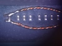
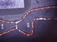
You can braid the 0.1 wires as I have often done (until the right one arrives).I’ve been keeping up as much as possible, but no, I haven’t read through 500 pages. I will order the .2 mm.
Attachments
So what would you suggest for the remaining wire? I ordered 36awg insulated a few days ago that should be here next week. Is that ok?
i use 0.2mm enamel wire for everything. works great.
Post automatically merged:
You can braid the 0.1 wires as I have often done (until the right one arrives).
It takes four 0.1mm wires to reach the same surface area as a 0.2mm wire, though.
- Joined
- Jul 12, 2010
- Messages
- 162
- Trophies
- 1
- Age
- 36
- Location
- Bananna Land.
- Website
- www.nerdfy.com.br
- XP
- 843
- Country

Well, this is my preliminary investigation results: a dat0 ripoff. @abal1000x @QuiTim
@Dee87

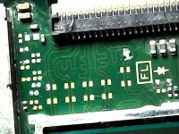
Well, my switch lite worked for four days after a "successful" pico install, full hekate's nand backup and etc.
In two different episodes I was some OS freezing... In the last freeze, I forced a power off, and since, black screen and the Led code was "*=* No eMMC block 0 read error" I checked that the wires had continuity, there was no grounding. So I removed the chip, the wires and now under the microscope I noticed that my dat0 was ripped out. I don't know if this happened during chip removal, after the black screen or if it was already like that. Could this be related to my black screen?
Thx for the help.
@Dee87

Well, my switch lite worked for four days after a "successful" pico install, full hekate's nand backup and etc.
In two different episodes I was some OS freezing... In the last freeze, I forced a power off, and since, black screen and the Led code was "*=* No eMMC block 0 read error" I checked that the wires had continuity, there was no grounding. So I removed the chip, the wires and now under the microscope I noticed that my dat0 was ripped out. I don't know if this happened during chip removal, after the black screen or if it was already like that. Could this be related to my black screen?
Thx for the help.
That 2 pad (Dat0) must be connected, The right point goes to the cpu the left point goes to the emmc.Well, this is my preliminary investigation results: a dat0 ripoff. @abal1000x @QuiTim
@Dee87
View attachment 377775
View attachment 377777
Well, my switch lite worked for four days after a "successful" pico install, full hekate's nand backup and etc.
In two different episodes I was some OS freezing... In the last freeze, I forced a power off, and since, black screen and the Led code was "*=* No eMMC block 0 read error" I checked that the wires had continuity, there was no grounding. So I removed the chip, the wires and now under the microscope I noticed that my dat0 was ripped out. I don't know if this happened during chip removal, after the black screen or if it was already like that. Could this be related to my black screen?
Thx for the help.
Since it is disconected, then the cpu can't access the emmc.
The fix is difficult, might takeout the emmc and made another cable (just like in oled) and connect it to the right pad of the Dat0 line.
Maybe someone else have a better opinionl, for the fix.
Editted:
It seems theres little bit copper in there you might be could soldered it to join the connection. Maybe with a little bit wire in there. After that use the alt point D0 for lite (in right area)
Last edited by abal1000x,
I'm using 2.74 on my OLED with slow / sporadic glitch times and it seems not much has changed that I can tell so far. Really stumped on what is causing it because I've been over every joint and changed from CPU flex cable to dual mosfets and nothing seems to make even the slightest difference to the glitch times. After updating the firmware I rebooted the Switch quite a few times and seems the average glitch time is still around 10 seconds. With highs of 20+ seconds and lows of ~2 seconds.
It has still never failed to glitch so far so that gives me a bit of confidence but it's not a great user experience having to potentially wait 20 seconds after pressing the power button for something to come up on the screen so I'm still not happy with it.
I've got a Lite doing the same and it doesn't seem like *you've gotten an answer, correct?
Yup, without Dat0 wires connected to pico it should boot straight to ofw, so the problem lies somewhere else or move to somewhere else (emmc corrupt?).And that could also make the black screen? It doesn't even boot to OFW now even after removing the new DAT0
Just try to desolder everything from pico and hope it will boot normally.
Post automatically merged:
Yup, that will result in black screen.Well, this is my preliminary investigation results: a dat0 ripoff. @abal1000x @QuiTim
@Dee87
View attachment 377775
View attachment 377777
Well, my switch lite worked for four days after a "successful" pico install, full hekate's nand backup and etc.
In two different episodes I was some OS freezing... In the last freeze, I forced a power off, and since, black screen and the Led code was "*=* No eMMC block 0 read error" I checked that the wires had continuity, there was no grounding. So I removed the chip, the wires and now under the microscope I noticed that my dat0 was ripped out. I don't know if this happened during chip removal, after the black screen or if it was already like that. Could this be related to my black screen?
Thx for the help.
If Cmd ripped out it will result purple screen.
For fix : use the thinnest wire you can found (0.01 is prefered), non enameled, Pre tin it, and make a tin blob on the solder tip, use as much flux you like, then start soldering.. only one second solder touch is needed.. you can know its conected if you cannot pull the wire.
First target is to solder the wire on to broken pads.. after that done, solder the other end of wire to good pad.
If the switch can boot, you can continue the mod using alternate dat0 point.
Last edited by cgtchy0412,
Solder balls!!!Any tips using the stencil?
It makes reballing so incredibly easy. I don't know why people torture themselves with solder paste.
0.3mm solder balls for the emmc.
Similar threads
- Replies
- 5
- Views
- 2K
- Replies
- 2
- Views
- 754
- Replies
- 42
- Views
- 7K
Site & Scene News
New Hot Discussed
-
-
35K views
New static recompiler tool N64Recomp aims to seamlessly modernize N64 games
As each year passes, retro games become harder and harder to play, as the physical media begins to fall apart and becomes more difficult and expensive to obtain. The... -
30K views
Nintendo officially confirms Switch successor console, announces Nintendo Direct for next month
While rumors had been floating about rampantly as to the future plans of Nintendo, the President of the company, Shuntaro Furukawa, made a brief statement confirming... -
27K views
Name the Switch successor: what should Nintendo call its new console?
Nintendo has officially announced that a successor to the beloved Switch console is on the horizon. As we eagerly anticipate what innovations this new device will... -
16K views
DOOM has been ported to the retro game console in Persona 5 Royal
DOOM is well-known for being ported to basically every device with some kind of input, and that list now includes the old retro game console in Persona 5 Royal... -
14K views
Mario Builder 64 is the N64's answer to Super Mario Maker
With the vast success of Super Mario Maker and its Switch sequel Super Mario Maker 2, Nintendo fans have long been calling for "Maker" titles for other iconic genres... -
14K views
Anbernic reveals the RG35XXSP, a GBA SP-inspired retro handheld
Retro handheld manufacturer Anbernic has revealed its first clamshell device: the Anbernic RG35XXSP. As the suffix indicates, this handheld's design is inspired by... -
14K views
Majora’s Mask PC port 2Ship2Harkinian gets its first release
After several months of work, the Harbour Masters 64 team have released their first public build of 2Ship2Harkinian, a feature-rich Majora's Mask PC port. This comes... -
12K views
"Nintendo World Championships: NES Edition", a new NES Remix-like game, launching July 18th
After rumour got out about an upcoming NES Edition release for the famed Nintendo World Championships, Nintendo has officially unveiled the new game, titled "Nintendo...by ShadowOne333 78 -
12K views
Microsoft is closing down several gaming studios, including Tango Gameworks and Arkane Austin
The number of layoffs and cuts in the videogame industry sadly continue to grow, with the latest huge layoffs coming from Microsoft, due to what MIcrosoft calls a...by ShadowOne333 65 -
11K views
Ubisoft reveals 'Assassin's Creed Shadows' which is set to launch later this year
Ubisoft has today officially revealed the next installment in the Assassin's Creed franchise: Assassin's Creed Shadows. This entry is set in late Sengoku-era Japan...
-
-
-
325 replies
Name the Switch successor: what should Nintendo call its new console?
Nintendo has officially announced that a successor to the beloved Switch console is on the horizon. As we eagerly anticipate what innovations this new device will...by Costello -
235 replies
Nintendo officially confirms Switch successor console, announces Nintendo Direct for next month
While rumors had been floating about rampantly as to the future plans of Nintendo, the President of the company, Shuntaro Furukawa, made a brief statement confirming...by Chary -
141 replies
New static recompiler tool N64Recomp aims to seamlessly modernize N64 games
As each year passes, retro games become harder and harder to play, as the physical media begins to fall apart and becomes more difficult and expensive to obtain. The...by Chary -
99 replies
Majora’s Mask PC port 2Ship2Harkinian gets its first release
After several months of work, the Harbour Masters 64 team have released their first public build of 2Ship2Harkinian, a feature-rich Majora's Mask PC port. This comes...by Scarlet -
96 replies
Ubisoft reveals 'Assassin's Creed Shadows' which is set to launch later this year
Ubisoft has today officially revealed the next installment in the Assassin's Creed franchise: Assassin's Creed Shadows. This entry is set in late Sengoku-era Japan...by Prans -
88 replies
The Kingdom Hearts games are coming to Steam
After a little more than three years of exclusivity with the Epic Games Store, Square Enix has decided to bring their beloved Kingdom Hearts franchise to Steam. The...by Chary -
78 replies
"Nintendo World Championships: NES Edition", a new NES Remix-like game, launching July 18th
After rumour got out about an upcoming NES Edition release for the famed Nintendo World Championships, Nintendo has officially unveiled the new game, titled "Nintendo...by ShadowOne333 -
71 replies
DOOM has been ported to the retro game console in Persona 5 Royal
DOOM is well-known for being ported to basically every device with some kind of input, and that list now includes the old retro game console in Persona 5 Royal...by relauby -
66 replies
Select PlayStation 2 games are coming to PlayStation 5
Sony is once more attempting to reintroduce players to their older library of games by re-releasing classic PlayStation 2 titles onto the PlayStation Store. During...by Chary -
65 replies
Microsoft is closing down several gaming studios, including Tango Gameworks and Arkane Austin
The number of layoffs and cuts in the videogame industry sadly continue to grow, with the latest huge layoffs coming from Microsoft, due to what MIcrosoft calls a...by ShadowOne333
-


