Hi, i was having issues with my previous 2.75 and it sometimes boots to ofw. I tried to reflash to 2.76 and now it keeps booting to ofw. How to reset it to make it train the chip for the 1st time ya? For some reason it doesn’t train the chip after reflash even i reflash back to 2.75I prefer 2.76.
2.75 already fixed the 'shutdown' issue though.
This is what i understand about the changelog of 2.76:
* Finer timing step for searching glitch point from 10 -> 8.
* Change algorithm of waiting for glitched identification on dat0.
* Change of the timing parameter when uploading data to the emmc via dat0.
(Its pretty drastic from 4248 to 527. I've no idea what is the impact. But i think it is modified by trial and error.)
You are using an out of date browser. It may not display this or other websites correctly.
You should upgrade or use an alternative browser.
You should upgrade or use an alternative browser.
Staff Posts
Recent threadmarks
sharing files
Important Posts
Recent threadmarks
Firmwareswhat model? oled?Hi, i was having issues with my previous 2.75 and it sometimes boots to ofw. I tried to reflash to 2.76 and now it keeps booting to ofw. How to reset it to make it train the chip for the 1st time ya? For some reason it doesn’t train the chip after reflash even i reflash back to 2.75
"sometimes boots to ofw"Hi, i was having issues with my previous 2.75 and it sometimes boots to ofw. I tried to reflash to 2.76 and now it keeps booting to ofw. How to reset it to make it train the chip for the 1st time ya? For some reason it doesn’t train the chip after reflash even i reflash back to 2.75
this might indicate the installation are not stable.
If it is, it cannot fixed by software, need to be solved on hardware solution.
Usually happened on flex dat0 adapter.
Especially if the switch got shake a lot, like in the transportation, or if the game is physical.
Need use a more solid solution like permanent dat0 using thin conductor, emmc adapter or drill method.
Hi, thanks for the response. Okay will check the dat0 adapter again. Thanks"sometimes boots to ofw"
this might indicate the installation are not stable.
If it is, it cannot fixed by software, need to be solved on hardware solution.
Usually happened on flex dat0 adapter.
Especially if the switch got shake a lot, like in the transportation, or if the game is physical.
Need use a more solid solution like permanent dat0 using thin conductor, emmc adapter or drill method.


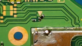
Hey guys... I'm back. and I think I fucked up. Please tell me this can be saved? tore the bottom pad
After a second glance it appears as though some of the pad is still there. Salvageable? I think I'm getting in too over my head here. Any person I can send this to and fix this mess?
After a second glance it appears as though some of the pad is still there. Salvageable? I think I'm getting in too over my head here. Any person I can send this to and fix this mess?
Attachments
Last edited by bmanzzs,
Dude you need a smaller package. You could probably get away with size 0603. Also you need a fine tip and tweezers to hold it, once you solder one end, the other end becomes easy.Hey guys... I'm back. and I think I fucked up. Please tell me this can be saved? tore the bottom pad
After a second glance it appears as though some of the pad is still there. Salvageable? I think I'm getting in too over my head here. Any person I can send this to and fix this mess?
This assumes you're not a total newbie.
If you are this is the correct procedure:
Get an iron rod and adjust it to 300C, slowly position it close enough to lift the old package. Rule of thumb, never forcefully lift anything off the pcb if you find resistance otherwise it will not end well. Once removed, add flux and tin the pads to make it easy to mount the new resistor. Clean and add small amount of flux just enough to see the mounting pads. Now take the new resistor and slowly place it in that position (flux will help you hold the bugger in place). Once positioned, slowly move your iron at one end until you notice it securing in place. Now do the same to the other end. Do not hold your iron for more than 2 sec otherwise you will transfer the heat melting both ends knocking away the resistor.
Last edited by Hassal,
Thank you for the advice, will try.Dude you need a smaller package. You could probably get away with size 0603. Also you need a fine tip and tweezers to hold it, once you solder one end, the other end becomes easy.
This assumes you're not a total newbie.
If you are this is the correct procedure:
Get an iron rod and adjust it to 300C, slowly position it close enough to lift the old package. Rule of thumb, never forcefully lift anything off the pcb if you find resistance otherwise it will not end well. Once removed, add flux and tin the pads to make it easy to mount the new resistor. Clean and add small amount of flux just enough to see the mounting pads. Now take the new resistor and slowly place it in that position (flux will help you hold the bugger in place). Once positioned, slowly move your iron at one end until you notice it securing in place. Now do the same to the other end. Do not hold your iron for more than 2 sec otherwise you will transfer the heat melting both ends knocking away the resistor.
Last edited by bmanzzs,
- Joined
- Sep 2, 2020
- Messages
- 1,320
- Trophies
- 0
- Age
- 39
- Location
- TORONTO
- Website
- form.jotform.com
- XP
- 2,259
- Country

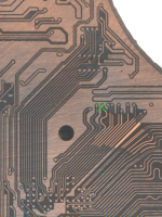
2layers front trace to the cpu, it is fixableHey guys... I'm back. and I think I fucked up. Please tell me this can be saved? tore the bottom pad
After a second glance it appears as though some of the pad is still there. Salvageable? I think I'm getting in too over my head here. Any person I can send this to and fix this mess?
Attachments
Easier to solder small resistors with a proper hot air station/rework station.
If you dont have a proper microscope when soldering.
Hold the resistor steady with tweezer and then apply hot air. Dont forget flux.
If you dont have a proper microscope when soldering.
Hold the resistor steady with tweezer and then apply hot air. Dont forget flux.
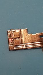
I'm pretty sure this is ok, but I'm asking because it never hurts.
I'm gonna use a flex for core V2 Switch on a oled by cutting it and soldering a wire directly to the 0 ohm resistor.
Soldering the wire to the circled point would be fine, right?
I'm gonna use a flex for core V2 Switch on a oled by cutting it and soldering a wire directly to the 0 ohm resistor.
Soldering the wire to the circled point would be fine, right?
Attachments
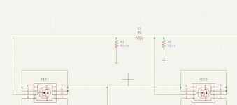
Connect line to 3rd resistorI'm pretty sure this is ok, but I'm asking because it never hurts.
I'm gonna use a flex for core V2 Switch on a oled by cutting it and soldering a wire directly to the 0 ohm resistor.
Soldering the wire to the circled point would be fine, right?
Attachments
Dude you need a smaller package. You could probably get away with size 0603. Also you need a fine tip and tweezers to hold it, once you solder one end, the other end becomes easy.
This assumes you're not a total newbie.
If you are this is the correct procedure:
Get an iron rod and adjust it to 300C, slowly position it close enough to lift the old package. Rule of thumb, never forcefully lift anything off the pcb if you find resistance otherwise it will not end well. Once removed, add flux and tin the pads to make it easy to mount the new resistor. Clean and add small amount of flux just enough to see the mounting pads. Now take the new resistor and slowly place it in that position (flux will help you hold the bugger in place). Once positioned, slowly move your iron at one end until you notice it securing in place. Now do the same to the other end. Do not hold your iron for more than 2 sec otherwise you will transfer the heat melting both ends knocking away the resistor.
2layers front trace to the cpu, it is fixable
Easier to solder small resistors with a proper hot air station/rework station.
If you dont have a proper microscope when soldering.
Hold the resistor steady with tweezer and then apply hot air. Dont forget flux.
Thank you everyone for all of the wonderful advice.
I have a magical video to share with y'all. I was at this for 2 hours last night without success, but I felt good turning on the iron today and somehow attached it in 5 min.
I ended up using a 10k ohm resistor, and knew it should be fine thanks to abal1000x's useful info. It's hard to see, but I guess there was enough pad left to attach both ends. I can't believe I almost gave up. You guys gave me the confidence I needed I think.
Now on to actually installing the mod chip once I get a replacement kit
Attachments
Last edited by bmanzzs,
Ah yes, the one going to 3rd and 4th pin on the flex. That would make the most sense but it's kinda uncomfortable to solder there because it's too squeezed against one of the mosfets.Connect line to 3rd resistor
Wouldn't it be just the same if I were to solder to R2, which is much easier to reach?
Yes.Soldering the wire to the circled point would be fine, right?
You can always use multimeter to find alternative points.
You could do that too, I'm just showing you the correct schematic.Ah yes, the one going to 3rd and 4th pin on the flex. That would make the most sense but it's kinda uncomfortable to solder there because it's too squeezed against one of the mosfets.
Wouldn't it be just the same if I were to solder to R2, which is much easier to reach?
I have read this thread from page one to page 627 (still ongoing, hahaha). There is a lot of interesting information about where to start and what tools are needed to begin. Truly a very beneficial group
Similar threads
- Replies
- 5
- Views
- 2K
- Replies
- 2
- Views
- 721
- Replies
- 42
- Views
- 7K
Site & Scene News
New Hot Discussed
-
-
34K views
New static recompiler tool N64Recomp aims to seamlessly modernize N64 games
As each year passes, retro games become harder and harder to play, as the physical media begins to fall apart and becomes more difficult and expensive to obtain. The... -
29K views
Nintendo officially confirms Switch successor console, announces Nintendo Direct for next month
While rumors had been floating about rampantly as to the future plans of Nintendo, the President of the company, Shuntaro Furukawa, made a brief statement confirming... -
26K views
Name the Switch successor: what should Nintendo call its new console?
Nintendo has officially announced that a successor to the beloved Switch console is on the horizon. As we eagerly anticipate what innovations this new device will... -
15K views
DOOM has been ported to the retro game console in Persona 5 Royal
DOOM is well-known for being ported to basically every device with some kind of input, and that list now includes the old retro game console in Persona 5 Royal... -
14K views
Mario Builder 64 is the N64's answer to Super Mario Maker
With the vast success of Super Mario Maker and its Switch sequel Super Mario Maker 2, Nintendo fans have long been calling for "Maker" titles for other iconic genres... -
13K views
Anbernic reveals the RG35XXSP, a GBA SP-inspired retro handheld
Retro handheld manufacturer Anbernic has revealed its first clamshell device: the Anbernic RG35XXSP. As the suffix indicates, this handheld's design is inspired by... -
12K views
Majora’s Mask PC port 2Ship2Harkinian gets its first release
After several months of work, the Harbour Masters 64 team have released their first public build of 2Ship2Harkinian, a feature-rich Majora's Mask PC port. This comes... -
12K views
"Nintendo World Championships: NES Edition", a new NES Remix-like game, launching July 18th
After rumour got out about an upcoming NES Edition release for the famed Nintendo World Championships, Nintendo has officially unveiled the new game, titled "Nintendo...by ShadowOne333 78 -
12K views
Microsoft is closing down several gaming studios, including Tango Gameworks and Arkane Austin
The number of layoffs and cuts in the videogame industry sadly continue to grow, with the latest huge layoffs coming from Microsoft, due to what MIcrosoft calls a...by ShadowOne333 65 -
11K views
Ubisoft reveals 'Assassin's Creed Shadows' which is set to launch later this year
Ubisoft has today officially revealed the next installment in the Assassin's Creed franchise: Assassin's Creed Shadows. This entry is set in late Sengoku-era Japan...
-
-
-
321 replies
Name the Switch successor: what should Nintendo call its new console?
Nintendo has officially announced that a successor to the beloved Switch console is on the horizon. As we eagerly anticipate what innovations this new device will...by Costello -
233 replies
Nintendo officially confirms Switch successor console, announces Nintendo Direct for next month
While rumors had been floating about rampantly as to the future plans of Nintendo, the President of the company, Shuntaro Furukawa, made a brief statement confirming...by Chary -
141 replies
New static recompiler tool N64Recomp aims to seamlessly modernize N64 games
As each year passes, retro games become harder and harder to play, as the physical media begins to fall apart and becomes more difficult and expensive to obtain. The...by Chary -
96 replies
Ubisoft reveals 'Assassin's Creed Shadows' which is set to launch later this year
Ubisoft has today officially revealed the next installment in the Assassin's Creed franchise: Assassin's Creed Shadows. This entry is set in late Sengoku-era Japan...by Prans -
94 replies
Majora’s Mask PC port 2Ship2Harkinian gets its first release
After several months of work, the Harbour Masters 64 team have released their first public build of 2Ship2Harkinian, a feature-rich Majora's Mask PC port. This comes...by Scarlet -
88 replies
The Kingdom Hearts games are coming to Steam
After a little more than three years of exclusivity with the Epic Games Store, Square Enix has decided to bring their beloved Kingdom Hearts franchise to Steam. The...by Chary -
78 replies
"Nintendo World Championships: NES Edition", a new NES Remix-like game, launching July 18th
After rumour got out about an upcoming NES Edition release for the famed Nintendo World Championships, Nintendo has officially unveiled the new game, titled "Nintendo...by ShadowOne333 -
71 replies
DOOM has been ported to the retro game console in Persona 5 Royal
DOOM is well-known for being ported to basically every device with some kind of input, and that list now includes the old retro game console in Persona 5 Royal...by relauby -
65 replies
Microsoft is closing down several gaming studios, including Tango Gameworks and Arkane Austin
The number of layoffs and cuts in the videogame industry sadly continue to grow, with the latest huge layoffs coming from Microsoft, due to what MIcrosoft calls a...by ShadowOne333 -
64 replies
Select PlayStation 2 games are coming to PlayStation 5
Sony is once more attempting to reintroduce players to their older library of games by re-releasing classic PlayStation 2 titles onto the PlayStation Store. During...by Chary
-
Popular threads in this forum
General chit-chat
- No one is chatting at the moment.
-
 @
Veho:
I don't give a fuck about what happens to America but I would like it if your shit didn't spill out on the rest of the world, thank you.+3
 -
-
 @
AncientBoi:
I give a fuck about what happens to America but I would like it if our shit didn't spill out on the rest of the world, thank you.+2
 -
-
 @
Psionic Roshambo:
@Veho, didn't need any news. Just going to the store and buying groceries is a constant reminder.
@
Psionic Roshambo:
@Veho, didn't need any news. Just going to the store and buying groceries is a constant reminder. -
-
-
 @
Veho:
Reminded that every single price gouging law was blocked by republicans because "muh gubmint overreach"?
 -
-
 @
Psionic Roshambo:
The problem with X party blocked X bill that would have prevented X is that yes the bill probably would have worked great, buuuttt they put XYZDCBG in said bill as an attempt to sneak things in that tend to be completely unrelated to the original bills intent. It sucks because if they would just do a single thing they could probably get something done...
 -
 @
Psionic Roshambo:
But congressman X needs to have government funding for his cousins unicycle business
 -
-
-
-
-
-
-
-
-
-
-
-
-
-








 Rotflmao