Unfortunately I don't have a tiny - so I can only go by the reference measurements - for reference here's the fly2040-min measurements next to the tiny's... (mine's smaller )
Also - I've just installed one (fly2040-min) and I can happily confirm it works perfectly.
The nice thing is that it also already has the 3 x 47 Ohm resistors, the boot button (which is also so small it doesn't have to be removed) and an optional mosfet pulldown resistor (10K). Just solder the jumper to use the pulldown.
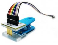
I'm going to release (in the same git) a programmer board. But the intention is to use a pogo-pins clip (Search ali for something like: "1.27mm 6P PCB Clip Clamp Fixture Probe Tool Programming Download Burning PCB Debugging Inspection Tool")
For testing I just cut a USB cable and put a 3V3 regulator on a prototyping board, ran D+ & D- through, GND & 3V3 to my clip.
Programmer board coming.
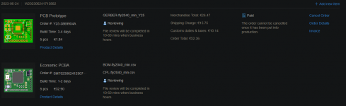
It's open source - https://github.com/floxcap/fly2040/tree/main/pcb/fly2040_min
But if there's enough interest I'll look at doing a bulk order at JLCPCB which will make pricing quite reasonable - and then I'd be happy to sell.
The pull down is connected to the solder jumper (normally disabled by default) and the other side of the jumper is connected to the CPU pad.
I'm going to release (in the same git) a programmer board. But the intention is to use a pogo-pins clip (Search ali for something like: "1.27mm 6P PCB Clip Clamp Fixture Probe Tool Programming Download Burning PCB Debugging Inspection Tool")
For testing I just cut a USB cable and put a 3V3 regulator on a prototyping board, ran D+ & D- through, GND & 3V3 to my clip.
Post automatically merged:
If you're doing quite a few of these - you only need 1 programmer set-up.
Of course also - once installed - the normal upgrade bin would be used.
Post automatically merged:
Programmer board coming.
It's open source - https://github.com/floxcap/fly2040/tree/main/pcb/fly2040_min
But if there's enough interest I'll look at doing a bulk order at JLCPCB which will make pricing quite reasonable - and then I'd be happy to sell.
The pull down is connected to the solder jumper (normally disabled by default) and the other side of the jumper is connected to the CPU pad. View attachment 377303
Not really... There's a potential for the mosfet(s) to carry a charge when the fly is in a sleep state or powering up. The (weak) pull-down is an option to ensure the mosfet(s) gate isn't floating at those times. The alternative is to have it at the mosfet side.
-Will you be selling these?
-If yes, how much will a board and flex cable order from you approximately cost?
-Does the latest fly2040_min board work on the Lite?
-Will you be selling these?
-If yes, how much will a board and flex cable order from you approximately cost?
-Does the latest fly2040_min board work on the Lite?
If there's enough interest - then I'd consider it.
Tested on the lite and on V2 and working perfectly.
Currently testing if it works with the mosfet(s) on the same board which will simplify the install and reduce the cost.
I'd be looking at selling for around $6 USD (but would probably set a minimum order amount because shipping is a hassle and I'm not doing it for profit).
Wonderful! I already found the flex cables in a shop in my country, so I won't have to import those as well. I will go order 5 of the min board then to install. Oh and one more thang, is the v2 the patched unit?(Detective Columbo Stinger)
Rapid Fire Edits: If I get the min boards for the lite, what HW_Fly CPU flex cable should I get as well? And how should I configure my order on JLC's site? Should I even get a flex cable?
Can you provide a photo with the best place to put the board on in the Lite and the solder spots?
It's an option if not using the CPU flex (v2 etc) cable... i.e. bare mosfet(s) install. The flex cable already has resistors.
I haven't used that option (jumper) yet as I'm waiting on mosfets to test bare mosfet install.
No I have, I am just asking for confirmation. And I am not aware of any documentation specific to the fly2040
Yes I am aware of the AIO thread and the pfg v6.2. I just want to make sure that I have all my tools at hand
After a couple days of Nintendo releasing their 18.0.0 firmware update, @SciresM releases a brand new update to his Atmosphere NX custom firmware for the Nintendo...
Today, April 8th, 2024, at 4PM PT, marks the day in which Nintendo permanently ends support for both the 3DS and the Wii U online services, which include co-op play...
Hello, GBAtemp members! After a prolonged absence, I am delighted to announce my return and upgraded form to you today...
Introducing tempBOT AI 🤖
As the embodiment...
With Apple having recently updated their guidelines for the App Store, iOS users have been left to speculate on specific wording and whether retro emulators as we...
The time has finally come, and after many, many years (if not decades) of Apple users having to side load emulator apps into their iOS devices through unofficial...
The highly popular and accurate FPGA hardware, MisterFGPA, has received today a brand new update with a long-awaited feature, or rather, a new core for hardcore...
A new Nintendo Switch firmware update is here. System software version 18.0.1 has been released. This update offers the typical stability features as all other...
The romhacking community is always a source for new ways to play retro games, from completely new levels or stages, characters, quality of life improvements, to flat...
Quite a bit of news have unfolded in the past couple of days in regards to the Sonic franchise, for both its small and big screens outings.
To start off, the...
In the month of March I had such lofty ideals, as I often do. I said to myself “I really want to beat Skyrim”, and I really did want to. I got the game downloaded...
Today, April 8th, 2024, at 4PM PT, marks the day in which Nintendo permanently ends support for both the 3DS and the Wii U online services, which include co-op play...
Hello, GBAtemp members! After a prolonged absence, I am delighted to announce my return and upgraded form to you today...
Introducing tempBOT AI 🤖
As the embodiment...
Nintendo might just as well be a law firm more than a videogame company at this point in time, since they have yet again issued their now almost trademarked usual...
After a couple days of Nintendo releasing their 18.0.0 firmware update, @SciresM releases a brand new update to his Atmosphere NX custom firmware for the Nintendo...
With Apple having recently updated their guidelines for the App Store, iOS users have been left to speculate on specific wording and whether retro emulators as we...
The time has finally come, and after many, many years (if not decades) of Apple users having to side load emulator apps into their iOS devices through unofficial...
A new Nintendo Switch firmware update is here. System software version 18.0.1 has been released. This update offers the typical stability features as all other...
Two classic titles join the Nintendo Switch Online Expansion Pack game lineup. Available starting April 24th will be the motorcycle racing game Extreme G and another...
The highly popular and accurate FPGA hardware, MisterFGPA, has received today a brand new update with a long-awaited feature, or rather, a new core for hardcore...
Nintendo has recently announced through their social media accounts that a new Indie World stream will be airing tomorrow, scheduled for April 17th, 2024 at 7 a.m. PT...


)