Tutorial  Updated

ANOTHER Magnetic Reed Switch RCM Installation

[TUTORIAL] [MOD] RCM mode with just a magnet (maghax). No visible changes to the Switch or Joycon!!! v1.7 2018-06-28

Please post any improvements or clarifications you'd like to see. If this passes muster, Mods can move it to the tutorials forum if appropriate.
v1.0
- beta tutorial
v1.1
- added some more text, and links to joycon teardowns
v1.2
- added reed dimensions
- added info about side affects and charging (there are no side effects)
v1.3
- added details on magnets
v1.4
- added more purchase options for magnetic reed switch
v1.5
- added link to https://gbatemp.net/threads/f-g-joycon-mod-magnethax-switch-edition.502459/ for credit to an older magnetic switch thread and instructions
v1.6
- added advise to disconnect battery before starting soldering.
v1.7
- added a user experience link at the bottom describing some more details.
-----------------------------------
This should be a pretty solid method for installing a MAGNETIC REED RELAY into your Right Joycon. the purpose is to have a cosmetically PERFECT Switch, with the ability to launch RCM with almost no effort. You just need to have a strong magnet to hold near the bottom right corner of the right joycon while you press power and volume + when booting. There are no known side affects of this method. i.e. you can still charge, use the joycon or switch normally. It's essentially stock when there is no magnet nearby and should last forever with no risk (after installation). I'd not send it in for warranty repair with the reed switch installed though :). This is a MUCH better option than a jig if you don't mind some soldering

The tutorial requires MODEST disassembly and soldering skill.

I'm not saying my approach and tutorial is any better than what other's have done (and posted). They certainly deserve credit. However, this is what I did and I think it's the best approach. I had previously posted a PSA about "why jigs are a bad idea" as I don't agree with them generally. So here is an explanation (for the reasonably skilled solderer) to do a magnetic reed switch the way I did it.

Note that much of the tutorial text is IN the spoilers with the pictures. Don't miss it. It is always at the top above the picture. I elected to keep this pretty visual rather than text, but happy to add more if people want more detail.

It is advisable to disconnect the joycon battery before starting to solder. I didn't disconnect the battery when I did the mod. So there isn't a picture of it.

IMG_20180521_200510 tool list.jpg
I didn't include info on how to open the case beyond showing the triwing screwdriver. There are better tutorials on opening the joycon VIDEO and TEXT
The reed switch can be bought from digikey for about $0.50 each. Shipping via USPS first class mail runs about $3 for under 8oz. The reed switch is 1.8mm by 10mm (body of the switch). HERE is an option from Amazon that is bigger (2mm x 14mm)

reeds only image.jpg
Note, I used 6cm wires. I wish I had cut them to about 3cm. You will see later they were a little too long. Also, I didn't take a picture of it, but I generally use the soldering iron to melt off 1mm of the wire end for soldering. I don't usually use wire strippers on Kynar insulated solid 30AWG wire. Note this is also called "wire wrap wire" in many circles.

IMG_20180521_201804 6cm wires.jpg
This is one of the main items different from what most people have done. This approach takes less space and allows the wires to exit the reed switch from the same side toward the connector. BE CAREFUL!!! It's VERY easy to break the glass on the reed switch when bending the leads. I broke two, though they were not ruined, I didn't want them chipped. Use some tweezers or needle nose pliers to bend it about 1mm beyond the end of the glass.

IMG_20180521_202311 bend.jpg
IMG_20180521_202524 solder.jpg
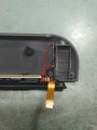
The goal here is to use enough heat shrink to cover the exposed leads and solder, but little enough that it doesn't interfere with placement. I went about 1/8" beyond the electrical connections on each end of the device.

IMG_20180521_202608_resize.jpg
Sorry I didn't get a better picture here!! It will give you the idea however.

IMG_20180521_203056 shrinkage.jpg
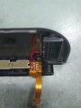
Be careful with the foam. It actually serves a purpose protecting the other side of the flex cable from abrasion against the soldered pins.

IMG_20180521_201134 remove foam.jpg
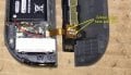
Here are pins 1 and 10 that you want to solder to. Be VERY careful. This is a tight soldering job and you don't want to mess up. You can still back out at this point if you aren't comfortable.

IMG_20180521_201220 solder points.jpg
IMG_20180521_203056 soldered.jpg
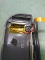
I think this is the best place to put it. The Joycon is pretty tight once assembled but there is ample room above the PCB and wire routing location where I have stuck it here.

IMG_20180521_203156 reed installed 1.jpg
IMG_20180521_203234 replace foam.jpg
If it isn't obvious, the way you know you did it right are with the below two tests, with and without magnet, and what you should see on the screen. Speaking of Magnets: I'd consider using a 1/4" or larger rare earth or "neodymium magnet" They come in different grades N35 N42 N50 etc. The higher the number the stronger. Any of them should work. The dark brown or black "ceramic" magnets work but they are not as strong so you might consider a larger size (maybe 1/2"??). Ebay has tons of them, Harbor Freight has rare earth magnets and magnetic grabber tools. Buymagnets.com is also an option but shipping might kill it.
IMG_20180521_203724_resize no magent.jpg
IMG_20180521_203750_resize with magnet.jpg

Here is a nice discussion of specific wire lengths and soldering technique as well as a way to use the kickstand to store the magnet [Post 84]
 

Attachments

  • IMG_20180521_201220 solder points.jpg
    IMG_20180521_201220 solder points.jpg
    185.6 KB · Views: 1,951
  • IMG_20180521_202608_resize.jpg
    IMG_20180521_202608_resize.jpg
    56.6 KB · Views: 1,787
Last edited by gallymimu,

gallymimu

EE Expert
OP
Member
Joined
Mar 15, 2009
Messages
466
Trophies
0
XP
699
Country
United States
So I got around to actually testing my reed switch yestersay, I've had issues getting into rcm, the magnet wasn't the issue for me but the placement of it.

It naturally wants to move to the taptic, after working out the correct placement it works perfectly, it feels better than jamming in a jig into the rail for sure.

Awesome.

Definitely need to be careful of placement unless you have a big ol' magnet.
 

ReavoEnd

Member
Newcomer
Joined
Jun 17, 2018
Messages
22
Trophies
0
Age
34
XP
173
Country
United States
OP's guide is spot-on. I took his comments about wire lengths to heart, starting with 3cm wires on each end of the reed switch, and achieved a super clean implementation.

Once the heat shrink was in place, I flattened the top and bottom of the tubing (heat —> pinch with fingers) and cut about 1/16ths inch off the top. To get the wires to the exact lengths needed to line up with pins 1 and 10, I cut 12mm off the lower wire (which appears longer after doing the heatshrink) and 11mm off off the upper wire. I secured the reed switch to the inside of the casing with a strip of 3mm-wide 3M double-sided red tape adhesive. Flattening the heatshrink really helped it stay in place against the casing.

The soldering was tricky. The method that worked best for me was to bend and position the wire tips exactly where I needed them against the pins, cut two roughly 2mm lengths of leaded solder, and used extra-fine-point tweezers to hold each nib of solder between the pin and the wire as I touch the iron to the solder. It should naturally bridge the two and cling onto the wire.

The end-result:

IMG_20180628_183257436.jpg

If you need a good excuse and means to keep a magnet with your Switch, look no further than the kickstand! If your kickstand is like mine and hardly ever stays tethered against the Switch, you can adhere a magnet to the underside of the kickstand's bottom edge and it will naturally gravitate towards the screw directly below the SD slot, when closed. Since the kickstand is also easy to remove, it is a good candidate for this extra purpose.

In my case I used one of the neodymium magnets found inside older iPads. These are about 1mm tall, 3.5-ish mm wide and some ~8mm long, and are a perfect fit for the bill. Again, 3mm red tape works well here, or you can likely employ a small dab of hot glue.

Thanks, OP, for your extremely detailed guide! You made this possible/more easily attainable for myself and many others.
 
Last edited by ReavoEnd,
  • Like
Reactions: gallymimu

gallymimu

EE Expert
OP
Member
Joined
Mar 15, 2009
Messages
466
Trophies
0
XP
699
Country
United States
OP's guide is spot-on. I took his comments about wire lengths to heart, starting with 3cm wires on each end of the reed switch, and achieved a super clean implementation.

Once the heat shrink was in place, I flattened the top and bottom of the tubing (heat —> pinch with fingers) and cut about 1/16ths inch off the top. To get the wires to the exact lengths needed to line up with pins 1 and 10, I cut 12mm off the lower wire (which appears longer after the heatshrink) and 11mm off off the upper wire. I secured the reed switch to the inside of the casing with a strip of 3mm-wide 3M double-sided red tape adhesive. Flattening the heatshrink really helped it stay in place against the casing.

The soldering was tricky. The method that worked best for me was to bend and position the wire tips exactly where I needed them against the pins, cut two roughly 2mm lengths of leaded solder, and held each nib of solder between the pin and the wire as I touch the iron to the solder. It should naturally bridge the two and cling onto the wire.

The end-result:

View attachment 133770

If you need a good excuse and means to keep a magnet with your Switch, look no further than the kickstand! If your kickstand is like mine and hardly ever stays tethered against the Switch, you can adhere a magnet to the underside of the kickstand's bottom edge and it will naturally gravitate towards the screw directly below the SD slot, when closed. Since the kickstand is also easy to remove, it is a good candidate for this extra purpose.

In my case I used one of the neodymium magnets found inside older iPads. These are about 1mm tall, 3.5-ish mm wide and some ~8mm long, and are a perfect fit for the bill. Again, 3mm red tape works well here, or you can likely employ a small dab of hot glue.

Thanks, OP, for your extremely detailed guide! You made this possible/more easily attainable for myself and many others.

Awesome, thanks for the compliment.

You made some great improvements!! I put a link to you post in the original post.

I will say I think your soldering approach might be harder than it needed to be. I typically use a little bit of leaded solder and add it to the pin joint to lower the melting temperature just a bit, then put a small amount of solder on the wire (just to "tin" it). Then I will heat the pin joint until wet, then "dip" the wire into it and remove the iron. Hold the wire steady until the joint solidifies.
 
Last edited by gallymimu,

ReavoEnd

Member
Newcomer
Joined
Jun 17, 2018
Messages
22
Trophies
0
Age
34
XP
173
Country
United States
Awesome, thanks for the compliment.

You made some great improvements!! I put a link to you post in the original post.

I will say I think your soldering approach might be harder than it needed to be. I typically use a little bit of leaded solder and add it to the pin joint to lower the melting temperature just a bit, then put a small amount of solder on the wire (just to "tin" it). Then I will heat the pin joint until wet, then "dip" the wire into it and remove the iron. Hold the wire steady until the joint solidifies.

Ha! You're so right. That definitely sounds easier. It may have been difficult for me - my soldering iron can't hold solder on the tip for whatever reason. Tip gets hot, but solder only sticks a little further back on the iron. Probably needs some tip tinner. I definitely recommend your method though, for those whose irons work properly!
 

gallymimu

EE Expert
OP
Member
Joined
Mar 15, 2009
Messages
466
Trophies
0
XP
699
Country
United States
Ha! You're so right. That definitely sounds easier. It may have been difficult for me - my soldering iron can't hold solder on the tip for whatever reason. Tip gets hot, but solder only sticks a little further back on the iron. Probably needs some tip tinner. I definitely recommend your method though, for those whose irons work properly!

your tip is shot. It's a common problem. You either have oxidation on the tip from overheating and improper care, or it's old and the protective tin plating has eroded away. I have had some luck restoring tips by heating them and scraping oxidation away with a knife and then re-tinning with solder. Tip tinner by itself PROBABLY won't help without scraping like I said or new tip.

Good luck!
 

underh1ll

New Member
Newbie
Joined
Jun 20, 2018
Messages
1
Trophies
0
Age
27
XP
283
Country
United Kingdom
Definitely need to be careful of placement unless you have a big ol' magnet.

Inspired by your mod, I replaced the Reed switch with an inexpensive 5mm Mercury Tilt switch from eBay; there's a nice little spot where you can lay it down almost horizontally between the + side of the battery and a screw a little further away.

The benefit is that it's a simple, clean install and no magnet needed, simply tilt the console away from you so that the usb port is facing you, press volume up and tap the power button.

Tips: use very thin, flexible wires to connect the tilt switch to the Joycon RCM solder points.
Also, just generally, apply a tiny bit of flux to the solder points to make soldering much easier.
 
Last edited by underh1ll,

gallymimu

EE Expert
OP
Member
Joined
Mar 15, 2009
Messages
466
Trophies
0
XP
699
Country
United States
Inspired by your mod, I replaced the Reed switch with an inexpensive 5mm Mercury Tilt switch from eBay; there's a nice little spot where you can lay it down almost horizontally between the + side of the battery and a screw a little further away.

The benefit is that it's a simple, clean install and no magnet needed, simply tilt the console away from you so that the usb port is facing you, press volume up and tap the power button.

Tips: use very thin, flexible wires to connect the tilt switch to the Joycon RCM solder points.
Also, just generally, apply a tiny bit of flux to the solder points to make soldering much easier.

Tilt switch is an amazing idea. That is really cool (wish I had thought of that!)
 

CraftyCanine

Member
Newcomer
Joined
Jul 10, 2018
Messages
5
Trophies
0
Age
34
XP
279
Country
United States
@gallymimu Long time lurker here. Created an account just to let you know that this tutorial inspired me to save my pins. Was able to buy all the items at my local Frys Electronics except for the reed switch. I've had my share of soldering projects but this one was definitely next level. I kept at it and eventually managed it! Now I can say goodbye to my jig! Thanks for sharing this with the community!
 

SeaK

New Member
Newbie
Joined
Apr 28, 2008
Messages
1
Trophies
0
XP
33
Country
United States
Great guide, i used a bigger wires than recommended so it was a tight fit but it still works. I removed the rail from the back of the joycon plastic and to give me more room for the soldering. Thanks for the detailed guide.
 
  • Like
Reactions: gallymimu

gallymimu

EE Expert
OP
Member
Joined
Mar 15, 2009
Messages
466
Trophies
0
XP
699
Country
United States
Great guide, i used a bigger wires than recommended so it was a tight fit but it still works. I removed the rail from the back of the joycon plastic and to give me more room for the soldering. Thanks for the detailed guide.

Glad you liked it. I am glad it worked with the thicker wire. I BET it as tough! It's really easy to use when yer done though right!
 

m2o94

New Member
Newbie
Joined
Sep 2, 2018
Messages
1
Trophies
0
Age
29
XP
63
Country
Italy
Good evening I joined now to thank gbqtemp.net and the creator of this post, I share the picture of how my technician placed the Reed swicth. He used the recommended wire and the 14mm Reed swicth.
 

Attachments

  • IMG-20180828-WA0011.jpg
    IMG-20180828-WA0011.jpg
    130.1 KB · Views: 410
  • IMG-20180828-WA0009.jpg
    IMG-20180828-WA0009.jpg
    138.9 KB · Views: 386
  • IMG-20180828-WA0008.jpg
    IMG-20180828-WA0008.jpg
    151.2 KB · Views: 352
Last edited by m2o94,

gallymimu

EE Expert
OP
Member
Joined
Mar 15, 2009
Messages
466
Trophies
0
XP
699
Country
United States
Buona sera mi sono iscritto adesso per ringraziare gbqtemp.net e il creatore di questo post, vi condivido la foto di come il mio tecnico a piazzato lo Reed swicth. Ha utilizato il filo consigliato e il Reed swicth da 14 mm.

Very nice, but please post in english :)

I am glad it worked for you!
 
Last edited by gallymimu,
  • Like
Reactions: CraftyCanine

kumikochan

Well-Known Member
Member
Joined
Feb 4, 2015
Messages
3,753
Trophies
0
Age
36
Location
Tongeren
XP
3,311
Country
Belgium
ha, that stuff isn't even "small" by electronics standards!

Glad it worked out for you though.
No it isn't but the one at the trigger was in such a bad spot that it was a bitch for me atleast to put back since it keep getting loose lol. The one just beneath the battery at the left side. Was havin trouble with that one actually
 
Last edited by kumikochan,

gemfire

New Member
Newbie
Joined
Oct 31, 2018
Messages
1
Trophies
0
Age
35
XP
45
Country
Romania
First time posting.
Long story short: I did this mod and now my joycon is not detected when it's attached, and won't charge, although it boots into rcm when a magnet is present.
I've desoldered the reed switch and then noticed that some of the pins under the joycon rail are bent inwards. Have no idea how that could've happened TBH, but I figured they are the problem and now I need a way to bend them back out.
Any ideas how I can do that?
Thanks.

IMG_8387.jpg
 

Site & Scene News

Popular threads in this forum

General chit-chat
Help Users
    BakerMan @ BakerMan: it looks like a little kids' game, and bunny (welcome btw) is looking for an uncensor patch