Switch oled not turning on after an attempted picofly installation

HexDev

New Member
OP
Newbie
Joined
Mar 2, 2024
Messages
3
Trophies
0
Age
24
XP
21
Country
Israel
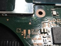
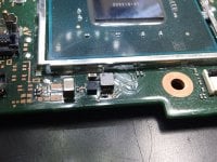
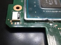
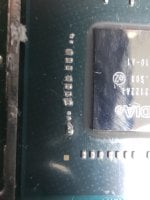
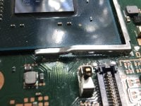
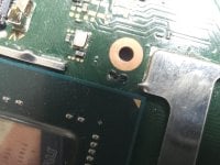
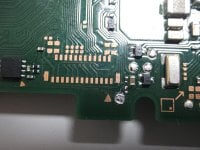
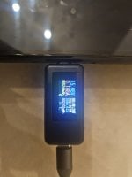
I tried to install the Picofly on my switch OLED and it was going great, all the connections were just right but the switch would not power on, i flashed my mod-chip and the switch still didn't turn on i tried powering the mod-chip externally and it kept doing two short flashes indicating that RST is not connected, i removed the mod chip and undid all of soldering, i did tons of research and checked the power regulator chip and a few test points and nothing seemed wrong, the via on the C point is intact, there are no shorts and nothing is getting hot, the voltages are correct, the APU is missing SP1 and SP2 and the cap to the right of SP2 is bridged however everyone told me that it would be fine but I'm starting to have doubts, is my APU dead? or is my button ribbon somehow faulty.
Post automatically merged:

ill upload pictures later
 
  • Like
Reactions: Subtle Demise

rull_bull

Well-Known Member
Newcomer
Joined
Nov 4, 2023
Messages
94
Trophies
0
Age
39
XP
259
Country
Sweden
You need to provide pictures of you want help.

And if sp1 and sp2 are gone + bridge next to it, then you will have to take close up pictures everywhere you have been soldering.

And also, pictures around the cpu shield/cover. Could be a broken trace around there
 

HexDev

New Member
OP
Newbie
Joined
Mar 2, 2024
Messages
3
Trophies
0
Age
24
XP
21
Country
Israel
You need to provide pictures of you want help.

And if sp1 and sp2 are gone + bridge next to it, then you will have to take close up pictures everywhere you have been soldering.

And also, pictures around the cpu shield/cover. Could be a broken trace around there
I didn't have my phone on me the time I made that post, but here are the images
 

Attachments

  • 20240303_184629.jpg
    20240303_184629.jpg
    1.6 MB · Views: 18
  • 20240303_184619.jpg
    20240303_184619.jpg
    1.4 MB · Views: 19
  • 20240303_184521.jpg
    20240303_184521.jpg
    1.2 MB · Views: 20
  • 20240303_184342.jpg
    20240303_184342.jpg
    1.4 MB · Views: 18
  • 20240303_184022.jpg
    20240303_184022.jpg
    1.5 MB · Views: 17
  • 20240303_183831.jpg
    20240303_183831.jpg
    1.6 MB · Views: 17
  • 20240303_183814.jpg
    20240303_183814.jpg
    1.5 MB · Views: 19
  • 20240303_183718.jpg
    20240303_183718.jpg
    815.5 KB · Views: 17
  • 20240303_183951.jpg
    20240303_183951.jpg
    1.6 MB · Views: 16
  • 20240303_184329.jpg
    20240303_184329.jpg
    1.4 MB · Views: 22
  • 20240303_184423.jpg
    20240303_184423.jpg
    1.5 MB · Views: 17

rull_bull

Well-Known Member
Newcomer
Joined
Nov 4, 2023
Messages
94
Trophies
0
Age
39
XP
259
Country
Sweden
And also you seem to have lots of mb damage around cpu shield.
Scratches/cuts, you need to clean and take better pictures on those places where you have copper showing.
I bet you have broken traces from the scratches you made trying to open the cpu shield.
 

HexDev

New Member
OP
Newbie
Joined
Mar 2, 2024
Messages
3
Trophies
0
Age
24
XP
21
Country
Israel
I have confirmed there are no cut traces around the CPU however I'm starting to think it's one of those ICs people talk about all the time because my switch has one of the symptoms (attached picture) but I also think that the bridged cap is what's causing it I still haven't been able to unbridge it and at this point I might just resort to cutting it in half and soldering a new one on top of it
 

Attachments

  • 20240401_200541.jpg
    20240401_200541.jpg
    1.5 MB · Views: 9

david watters

Active Member
Newcomer
Joined
Oct 18, 2013
Messages
30
Trophies
1
Age
35
Location
Inwood, Florida
XP
349
Country
United States
I have confirmed there are no cut traces around the CPU however I'm starting to think it's one of those ICs people talk about all the time because my switch has one of the symptoms (attached picture) but I also think that the bridged cap is what's causing it I still haven't been able to unbridge it and at this point I might just resort to cutting it in half and soldering a new one on top of it
are you talking about the 2 caps bridged in the picture? where it says f-2 on the board? if thats it then those bridges are fine as the are on the same rail.

i would look closer at the resistor by the reset point on the back of the board. cant tell from the picture but looks almost bridged across the resistor.

.188 amps is a sign your not getting past 1st stage boot. check the clock line to make sure its not grounded like said prior. check that your getting all of your 1st stage voltage rails.

for the short on the cap by sp2 get some decent tweezers and lightly pick at the solder. you will eventually get through it just dont press too hard and rip the cap off.
 

Site & Scene News

Popular threads in this forum

General chit-chat
Help Users
    K3Nv2 @ K3Nv2: Lol rappers still promoting crypto