


I've already soldered the APU pins as well.Without microscope, i strongly recommend using flex then manually soldering the mosfet.
Not worth the risk.
I just hope it'll work
")
I've already soldered the APU pins as well.Without microscope, i strongly recommend using flex then manually soldering the mosfet.
Not worth the risk.
I would resolder the bottom apu pin its pretty close to the second one.I've already soldered the APU pins as well.
I just hope it'll work
nice job ! no cuts in the shield.. I like thatI finished another installation, happier every day
! May I know what wire you use? marking .. or a direct link? How is this looking? First time soldering at that scale.
I don't have a microscope or anything, just my phone.
Still waiting for my mosfets, they'll arrive today.
What is community opinion on one vs two mosfets?
I would def agree here u might get it to work with a phoneWithout microscope, i strongly recommend using flex then manually soldering the mosfet.
Not worth the risk.
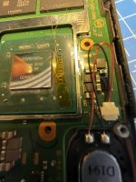
Thanks for the hint, I moved the wire a bit, so it avoids the second cap.I would resolder the bottom apu pin its pretty close to the second one.
Plus the pins don't really seem properly connected , maybe its the picture but make sure u have good contact.
The coating should be of completely and not on only one side, an solder should be around the whole uncoted enameled wire
Seems better the best way to get the coating off of the enameled wire is when u set ur soldering iron to 320+ ad a nice thick solderblob to ur iron and hold the wire in the solder blob on the iron for a few sec just only as deep as u want the solder on the wire otherwise just cut a peace of if u have to much uncoated.Thanks for the hint, I moved the wire a bit, so it avoids the second cap.
I'm really not sure about connection quality. I have a hard time getting solder to stick on the wires.
Hello, where does it say the 1k resistor? Couldn't find it in the v6.1 guideWhat do you mean by pull down resistor? The ones attached to the RP2040 in the guide?
EDIT: just found it. >1k resistor from gate to ground.
*== No eMMC CMD1 request (poor wiring, or dead CPU)Hello, where does it say the 1k resistor? Couldn't find it in the v6.1 guide
Do you guys think the SCL wires could fix the *== error?
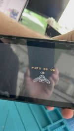
Thanks. Assuming CLK trace is cut off. I'm going to get this error, right?*== No eMMC CMD1 request (poor wiring, or dead CPU)
No it doesn't.
SDA SCL use if the normal glitch doesn't work.
Those error is before glitch stage. It still on the EMMC stage.
Unfortunately highly probable that pico doesn't receive the CLK.Thanks. Assuming CLK trace is cut off. I'm going to get this error, right?
Thanks. No, I get the error with a black screen.Unfortunately highly probable that pico doesn't receive the CLK.
The error means theres no emmc activity detected by the pico.
If it is CMD, DAT0 whose disconnected, the firmware will detect it, and the error code will be different. So if the CMD, Dat0 connected, then theres left the CLK.
Can you go to the OFW after pico failed with those error?
Post automatically merged:
@rehius
I read from the "Led Indication" that there is CLK error code:
== CLK is not connected
But couldn't find the code in the firmware which detect it.
Am i missing something?
Yes make a sense.Thanks. No, I get the error with a black screen.
I'm thinking if I got that error again, I'm going to jump wire from the eMMC CLK point to the trace just to get to OFW. Makes sense?
I've never had such an issue with an OLED, I got a blue screen before, but not black. reason being; This was my first OLED install with my new station,SUGON A9, I should have practiced on a donor board to get an idea of its heating capacity.Yes make a sense.
The no activity might occured because it is not connected to the cpu.
Thought this might help if at all:I've never had such an issue with an OLED, I got a blue screen before, but not black. reason being; This was my first OLED install with my new station,SUGON A9, I should have practiced on a donor board to get an idea of its heating capacity.
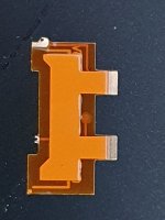
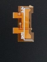
Unfurtunately yes, but i think you can still use them if you want. Use @abal1000x method, cut the left part flush and the right part of the pin should fit between the dat0 and the 2nd ball (nc). Maybe you need to move the whole adapter slightly (0.05-0.01) to the right.Need a second opinion. Are these the dog shite ones right!? Just got these today.....
Nah, going to complain and then order some stencils for emmc. That's the last time I order this type of crap. Not risking good hardware with this type of flimsy crap.Unfurtunately yes, but i think you can still use them if you want. Use @abal1000x method, cut the left part flush and the right part of the pin should fit between the dat0 and the 2nd ball (nc). Maybe you need to move the whole adapter slightly (0.05-0.01) to the right.
Holy crap it works!Thanks for the hint, I moved the wire a bit, so it avoids the second cap.
I'm really not sure about connection quality. I have a hard time getting solder to stick on the wires.
Nah, going to complain and then order some stencils for emmc. That's the last time I order this type of crap. Not risking good hardware with this type of flimsy crap.

What do you mean by pull down resistor? The ones attached to the RP2040 in the guide?
EDIT: just found it. >1k resistor from gate to ground.


 like a 250 dollar kit back when DDR4 was Intel only