

You are using an out of date browser. It may not display this or other websites correctly.
You should upgrade or use an alternative browser.
You should upgrade or use an alternative browser.
Staff Posts
Recent threadmarks
sharing files
Important Posts
Recent threadmarks
Firmwares

Not of the screen.View attachment 374753
Here. Well, for about a month everything worked fine. Now I have disconnected all contacts from the rp2040 altogether, but I still get this screen.
The motherboard with the pico.
And did you check for @Dee87 advice on checking the resistor values?
Edit - hmmm everythings disconnected now but still pink. Let me do some research on this pink/purple screen.
Attachments


Not of the screen.
The motherboard with the pico.
And did you check for @Dee87 advice on checking the resistor values?
Edit - hmmm everythings disconnected now but still pink. Let me do some research on this pink/purple screen.
I completely disabled the board and still get this screen
Its your cmd resistor i bet eather its not connected properly or it doesnt have the correct calue anymore

Oh no... I don't see a flex, and I doubt you put a pull-down resistor across mosfets before removing the pico...
Yep, my research pointed to the same conclusion. 'CMD resistor - 4.7k 0201'Its your cmd resistor i bet eather its not connected properly or it doesnt have the correct calue anymore
Check in resistance mode for that value but more than likely its blown so get that replaced (most likely).
Post automatically merged:
Good point, @Makc16384 did you use single or double mosfet and did you have a pull down resistor on your mosfet build!? Because you could potentially replace the resistor and fix the issue but a month down the line, the pink screen could return. Can you show us a picture of what your APU looks like under the hood (metal shield) and your mosfet build.Oh no... I don't see a flex, and I doubt you put a pull-down resistor across mosfets before removing the pico...
Another point, did you kapton tape/solder mask your solder joints your pico when you finished the install. I mean all around the points of the pico that were not used because they could cause shorts with the metal shielding above and below too.
Last edited by Takezo-San,
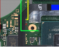
Replace the CMD resistorView attachment 374753
Here. Well, for about a month everything worked fine. Now I have disconnected all contacts from the rp2040 altogether, but I still get this screen.
Yep, my research pointed to the same conclusion. 'CMD resistor - 4.7k 0201'
Check in resistance mode for that value but more than likely its blown so get that replaced (most likely).
Post automatically merged:
Good point, @Makc16384 did you use single or double mosfet and did you have a pull down resistor on your mosfet build!? Because you could potentially replace the resistor and fix the issue but a month down the line, the pink screen could return. Can you show us a picture of what your APU looks like under the hood (metal shield) and your mosfet build.
Another point, did you kapton tape/solder mask your solder joints your pico when you finished the install. I mean all around the points of the pico that were not used because they could cause shorts with the metal shielding above and below too.

4k7 CMD resistor (but it usually happens during installation as it was in my case, check resistance, in diode mode you shoulkd have ~700 on one side=point A and ~300 on its other side) or this https://gbatemp.net/threads/no-more-old-hwfly-chip-new-rev-on-rp2040.632243/post-10161664Here. Well, for about a month everything worked fine. Now I have disconnected all contacts from the rp2040 altogether, but I still get this screen.
Last edited by Relon,
I checked the resistor. This resistance in one direction is 8.3k, in the other 77k. Apparently it’s really him, I’ll buy it as you said and put it. And what resistor is recommended between the G and S points of the MOSFET?Yep, my research pointed to the same conclusion. 'CMD resistor - 4.7k 0201'
Check in resistance mode for that value but more than likely its blown so get that replaced (most likely).
Post automatically merged:
Good point, @Makc16384 did you use single or double mosfet and did you have a pull down resistor on your mosfet build!? Because you could potentially replace the resistor and fix the issue but a month down the line, the pink screen could return. Can you show us a picture of what your APU looks like under the hood (metal shield) and your mosfet build.
Another point, did you kapton tape/solder mask your solder joints your pico when you finished the install. I mean all around the points of the pico that were not used because they could cause shorts with the metal shielding above and below too.
Looks clean but I do not see the presence of a resistor between gate and source. First is too replace the resistor.
3 optional options after that:
- Add a resistor to the mosfet
- Or add another mosfet so its a dual setup
- Or add another mosfet with a resistor in dual setup.
Hope that helps.
Post automatically merged:
Let me do some research on the actual resistor location because those values seem way to high and you don't want to be removing the wrong component.I checked the resistor. This resistance in one direction is 8.3k, in the other 77k. Apparently it’s really him, I’ll buy it as you said and put it. And what resistor is recommended between the G and S points of the MOSFET?
anywhere between 1k - 1mhz. I used 10k, others have used 3k others have used 1k. Main point is, put a pull down resistor there because if not, that leave the current floating, which can cause the mosfet to be partly on for a while. If it's a high-current load, the mosfet can be destroyed.
Check if the mosfet still works and if it does, i would add a 1k to it, if it doesn't I would go ahead and add another mosfet with a resistor on the new build.
Edit - im sure this is the 'cmd resistor' (attached)
Attachments
Last edited by Takezo-San,

Thanks for every one help.i found one wier cpu on pico chip is Disconnect when im soldring sp1 sp2. Now is time for nand packup.
Hello, I come to you once again. I bought a Zelda edition console, I proceeded to test it, everything worked fine, I took it apart and started to install picofly, once installed it gave me a clk/CMD error with fw2.67 (the colors of both errors are very similar, so I don't I knew how to identify which one it was exactly) I proceeded to change the wiring of both points and it was still the same, a user suggested I use the most recent fw, I did, now apparently it gives an error in RST, I changed the RST cable to verify that there was continuity in both points and still it keeps giving me an error, what seems strange to me is that clk and cmd give me strange values and I don't know why, if someone can help me please I would appreciate itLatest firmware here
ChangeLog:
v2.0 + Active MMC communication
v2.1 + Toshiba support
v2.2 + Fix Toshiba boot fail
v2.3 + SanDisk support
v2.4 + Faster Toshiba boot
v2.5 + fix OFW boot
v2.6 + software update, xiao & itsy support
v2.61 + Instinct-NX sdloader, bug fixes
v2.62 + Make 16.0.1 happy (fix OFW boot)
v2.63 + roll back some 2.62 boot speed tricks
v2.64 + enable back the board detection
v2.65 + RP Pico support, double reset removed
v2.66 + Bypass to OFW after update for proper fuse burning
v2.67 + Don't bypass to OFW on first install
v2.70 + new LED indication, i2c undervoltage hack
v2.71 + support for SQc open-source board
v2.72 + disable CLK check, it's unstable
v2.73 + add LED signal on success
v2.74 + 300 mhz precision
= is long pulse, * is short pulse:
= USB flashing done
** RST is not connected
*= CMD is not connected
=* D0 is not connected
== CLK is not connected
*** No eMMC CMD1 responce (bad eMMC?)
**= No eMMC block 1 read (should not happen)
*=* No eMMC block 0 read (eMMC init failure?)
*== No eMMC CMD1 request (poor wiring, or dead CPU)
=** eMMC init failure during glitch process
=*= CPU never reach BCT check, should not happen
==* CPU always reach BCT check (no glitch reaction, check mosfet)
=== Glitch attempt limit reached, cannot glitch
=*** eMMC init failure
=**= eMMC write failure - comparison failed
=*=* eMMC write failure - write failed
=*== eMMC test failure - read failed
==** eMMC read failed during firmware update
==*= BCT copy failed - write failure
===* BCT copy failed - comparison failure
==== BCT copy failed - read failure
If your glitch is unstable (==* error), and the proper boot happens only when you press Reset after joycon logo, you can add two more wires to make glitch much better.
board pins:
Waveshare rp2040: SDA=12, SCL=13
Pi Pico: SDA = 19, SCL = 20
XIAO 2040: SDA=3, SCL=4
ItsyBitsy 2040: SDA = 18, SCL = 19
NS points (v2, Lite, OLED):
View attachment 372191
View attachment 372192
View attachment 372193
Q: What is supported?
A: Erista (v1), Mariko (v2, Lite, OLED)
Q: eMMC types support?
A: Tested on Hynix, Samsung, Toshiba, SanDisk
Q: rp2040 boards support
A: WaveShare 2040-zero/one, xiao-rp2040, adafruit itsybitsy (Pi Pico is not supported for now)
Q: GREEN, but instant reset
A: Clean flux near the RST point
Q: Do I really need 47 Ohm resistors?
A: You can skip them, however in this case you will have to use emuMMC due to the line interference, sysNAND would not boot (sysNAND data can be damaged).
Q: Does the firmware has learning? How to reset statistics
A: Short pin 0 to either 1 or GND during start for chip reset. The statistics is collected each boot. The more you start it - the better it boots.
Q: open source?
A: https://github.com/rehius
Q: why you made it?
A: to prove it possible!
Q: run Atmosphere?
A: no piracy
v2.5 firmware had a bug with BOOT0 corruption. To recover it:
- boot "Full Stock" using hekate
- update to the latest official firmware over Wi-Fi
- boot "Full Stock" using hekate
- perform a full system reset
- show firmware information
- update firmware from SD card (place update.bin into the root folder)
- rollback to the backup firmware slot
- reset learning statistics
- dump / write sdloader
if you have an rp2040-zero from waveshare/ali then it has a neopixel. It is used for diagnosing proper firmware flashes as well as console glitching. If you plug it in, and flash the uf2 firmware to it and immediately see a red light after flashing (this is not the same as flashing, then unplugging and replugging), then no rgb jumper needs to be made. If on the other hand, you get one quick green flashing light, then you need to bridge the jumper pads indicated to swap the LED colors for proper diagnoses capability.
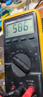
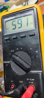
 seriously I'm desperate, I already changed the wiring it originally had. I want to cry, the images are of the values in clk and cmd
Attachments

First update firmware to latest version from the post you quoted and make a video of Pico booting then we'll see whats going onHello, I come to you once again. I bought a Zelda edition console, I proceeded to test it, everything worked fine, I took it apart and started to install picofly, once installed it gave me a clk/CMD error with fw2.67 (the colors of both errors are very similar, so I don't I knew how to identify which one it was exactly) I proceeded to change the wiring of both points and it was still the same, a user suggested I use the most recent fw, I did, now apparently it gives an error in RST, I changed the RST cable to verify that there was continuity in both points and still it keeps giving me an error, what seems strange to me is that clk and cmd give me strange values and I don't know why, if someone can help me please I would appreciate it
I am using the latest firmware, in my answer is the video, here is a more complete oneFirst update firmware to latest version from the post you quoted and make a video of Pico booting then we'll see whats going on
Attachments
- Joined
- Sep 2, 2020
- Messages
- 1,270
- Trophies
- 0
- Age
- 39
- Location
- TORONTO
- Website
- form.jotform.com
- XP
- 2,202
- Country

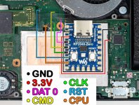
ARE you still making cpu line to rp2040 pin26 and RST to pin15?Hello, I come to you once again. I bought a Zelda edition console, I proceeded to test it, everything worked fine, I took it apart and started to install picofly, once installed it gave me a clk/CMD error with fw2.67 (the colors of both errors are very similar, so I don't I knew how to identify which one it was exactly) I proceeded to change the wiring of both points and it was still the same, a user suggested I use the most recent fw, I did, now apparently it gives an error in RST, I changed the RST cable to verify that there was continuity in both points and still it keeps giving me an error, what seems strange to me is that clk and cmd give me strange values and I don't know why, if someone can help me please I would appreciate it
Wake up! CPU to pin15 and RST on the PIN26
Attachments
@SorataVP69 wrote 'a user suggested I use the most recent fw, I did, now apparently it gives an error in RST'....First update firmware to latest version from the post you quoted and make a video of Pico booting then we'll see whats going on
My bad, for some reason the video was showing still on my phone. Let's see...I am using the latest firmware, in my answer is the video, here is a more complete one
Last edited by QuiTim,
You are absolutely right, I just put the cpu at 15 and the RST at 26 and everything works, forgive me for making a whole post looking like a drama queen, NOW IT WORKS, THANKS AND SORRY FOR THE INCONVENIENCEARE you still making cpu line to rp2040 pin26 and RST to pin15?
Wake up! CPU to pin15 and RST on the PIN26
Similar threads
- Replies
- 3
- Views
- 905
- Replies
- 42
- Views
- 5K
- Replies
- 5
- Views
- 1K
- Replies
- 6
- Views
- 2K
- Replies
- 8
- Views
- 2K
Site & Scene News
New Hot Discussed
-
-
26K views
Atmosphere CFW for Switch updated to pre-release version 1.7.0, adds support for firmware 18.0.0
After a couple days of Nintendo releasing their 18.0.0 firmware update, @SciresM releases a brand new update to his Atmosphere NX custom firmware for the Nintendo...by ShadowOne333 107 -
21K views
Wii U and 3DS online services shutting down today, but Pretendo is here to save the day
Today, April 8th, 2024, at 4PM PT, marks the day in which Nintendo permanently ends support for both the 3DS and the Wii U online services, which include co-op play...by ShadowOne333 179 -
17K views
GBAtemp Exclusive Introducing tempBOT AI - your new virtual GBAtemp companion and aide (April Fools)
Hello, GBAtemp members! After a prolonged absence, I am delighted to announce my return and upgraded form to you today... Introducing tempBOT AI 🤖 As the embodiment... -
13K views
The first retro emulator hits Apple's App Store, but you should probably avoid it
With Apple having recently updated their guidelines for the App Store, iOS users have been left to speculate on specific wording and whether retro emulators as we... -
13K views
Pokemon fangame hosting website "Relic Castle" taken down by The Pokemon Company
Yet another casualty goes down in the never-ending battle of copyright enforcement, and this time, it hit a big website which was the host for many fangames based and...by ShadowOne333 66 -
13K views
MisterFPGA has been updated to include an official release for its Nintendo 64 core
The highly popular and accurate FPGA hardware, MisterFGPA, has received today a brand new update with a long-awaited feature, or rather, a new core for hardcore...by ShadowOne333 54 -
13K views
Delta emulator now available on the App Store for iOS
The time has finally come, and after many, many years (if not decades) of Apple users having to side load emulator apps into their iOS devices through unofficial...by ShadowOne333 96 -
11K views
"TMNT: The Hyperstone Heist" for the SEGA Genesis / Mega Drive gets a brand new DX romhack with new features
The romhacking community is always a source for new ways to play retro games, from completely new levels or stages, characters, quality of life improvements, to flat...by ShadowOne333 36 -
10K views
Nintendo Switch firmware update 18.0.1 has been released
A new Nintendo Switch firmware update is here. System software version 18.0.1 has been released. This update offers the typical stability features as all other... -
10K views
Anbernic announces RG35XX 2024 Edition retro handheld
Retro handheld manufacturer Anbernic is releasing a refreshed model of its RG35XX handheld line. This new model, named RG35XX 2024 Edition, features the same...
-
-
-
179 replies
Wii U and 3DS online services shutting down today, but Pretendo is here to save the day
Today, April 8th, 2024, at 4PM PT, marks the day in which Nintendo permanently ends support for both the 3DS and the Wii U online services, which include co-op play...by ShadowOne333 -
169 replies
GBAtemp Exclusive Introducing tempBOT AI - your new virtual GBAtemp companion and aide (April Fools)
Hello, GBAtemp members! After a prolonged absence, I am delighted to announce my return and upgraded form to you today... Introducing tempBOT AI 🤖 As the embodiment...by tempBOT -
107 replies
Atmosphere CFW for Switch updated to pre-release version 1.7.0, adds support for firmware 18.0.0
After a couple days of Nintendo releasing their 18.0.0 firmware update, @SciresM releases a brand new update to his Atmosphere NX custom firmware for the Nintendo...by ShadowOne333 -
98 replies
Nintendo takes down Gmod content from Steam's Workshop
Nintendo might just as well be a law firm more than a videogame company at this point in time, since they have yet again issued their now almost trademarked usual...by ShadowOne333 -
97 replies
The first retro emulator hits Apple's App Store, but you should probably avoid it
With Apple having recently updated their guidelines for the App Store, iOS users have been left to speculate on specific wording and whether retro emulators as we...by Scarlet -
96 replies
Delta emulator now available on the App Store for iOS
The time has finally come, and after many, many years (if not decades) of Apple users having to side load emulator apps into their iOS devices through unofficial...by ShadowOne333 -
73 replies
Nintendo Switch firmware update 18.0.1 has been released
A new Nintendo Switch firmware update is here. System software version 18.0.1 has been released. This update offers the typical stability features as all other...by Chary -
66 replies
Pokemon fangame hosting website "Relic Castle" taken down by The Pokemon Company
Yet another casualty goes down in the never-ending battle of copyright enforcement, and this time, it hit a big website which was the host for many fangames based and...by ShadowOne333 -
54 replies
MisterFPGA has been updated to include an official release for its Nintendo 64 core
The highly popular and accurate FPGA hardware, MisterFGPA, has received today a brand new update with a long-awaited feature, or rather, a new core for hardcore...by ShadowOne333 -
53 replies
Nintendo Switch Online adds two more Nintendo 64 titles to its classic library
Two classic titles join the Nintendo Switch Online Expansion Pack game lineup. Available starting April 24th will be the motorcycle racing game Extreme G and another...by Chary
-
Popular threads in this forum
General chit-chat
-
 OctoAori20
Loading…
OctoAori20
Loading… -
 Veho
Loading…
Veho
Loading… -
 Psionic Roshambo
Loading…
Psionic Roshambo
Loading…
-
-
-
-
-
 @
Julie_Pilgrim:
@Psionic Roshambo i have 16 gb in my pc and i run into issues with ram more than i'd like to admit
@
Julie_Pilgrim:
@Psionic Roshambo i have 16 gb in my pc and i run into issues with ram more than i'd like to admit -
-
-
-
-
-
 @
Sonic Angel Knight:
Or, I also heard that if you use flash memory, it can act as more "RAM" at least windows tell me when I stick a flash drive into it.
@
Sonic Angel Knight:
Or, I also heard that if you use flash memory, it can act as more "RAM" at least windows tell me when I stick a flash drive into it. -
-
-
-
-
-
-
-
-
-
-
-
-
-