Picofly AIO Thread

Dee87

Well-Known Member
Member
Joined
Mar 19, 2023
Messages
1,139
Trophies
1
XP
1,578
Country
Germany
then the picture i created is correct
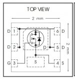
as the picture bevor yes , just remember when u remove a cap and lay the mosfett on top of a solder pad u need to isolate the pad otherwise some contacts of the mosfet might create a unwanted connection
Post automatically merged:

I see, a fast site that ships quickly?
Does Amazon sell rp2040, mosfets and resistors?
go to ur amazon site and check it
most likley they will
 
  • Like
Reactions: Banex and Ricky_25

linuxares

The inadequate, autocratic beast!
Global Moderator
Joined
Aug 5, 2007
Messages
13,365
Trophies
2
XP
18,260
Country
Sweden
Very true, but when the things are easily available it lowers the bar to entry and everyone thinks they can do it.
That's very true. Plus easier to find the parts and no need to rely on no-name-china team that we never know when they stop producing their modchips.
 
  • Like
Reactions: Ricky_25

cicci084

Well-Known Member
Member
Joined
Apr 1, 2023
Messages
146
Trophies
0
Age
44
XP
239
Country
Italy
Curiosity.
Using the mosfets, are the capacitors removed because their function is reproduced by the mosfets themselves or for other reasons?
 

Ganesha0112

Well-Known Member
Newcomer
Joined
Jan 22, 2023
Messages
56
Trophies
0
Age
28
XP
286
Country
Mexico
It’s already safe install this mod? I mean, I read before that the software isn’t sable and may cause some problems on the switch, it’s already to use as alternative to HWFLY? Or still need more development?
 

KingMo5h

Active Member
Newcomer
Joined
Mar 12, 2023
Messages
26
Trophies
0
Age
33
XP
139
Country
Germany
thanks to Dee87 in advanced for helping
i made this ...i hope helps others
View attachment 362718
Post picture Edited
I would say that the gate (G) is the CPU Line. As i understood right, we just shorten the cap to ground. Drain (D) and Source (S) are the pins of the cap. See attachement.

Edit: Also looks like its cap nr.9 that needs to be removed and not 8, at least it looks like it in the picture you send.
 

Attachments

  • irfhs8342.JPG
    irfhs8342.JPG
    29.1 KB · Views: 44
Last edited by KingMo5h,
  • Like
Reactions: Dee87

Banex

Member
Newcomer
Joined
Mar 25, 2023
Messages
13
Trophies
0
Age
48
XP
66
Country
Iran
I would say that the gate (G) is the CPU Line. As i understood right, we just shorten the cap to ground. Drain (D) and Source (S) are the pins of the cap. See attachement.
well got some help from dear Dee87 and some info this pic that posted before

about DAT0 im trying figure something without desolrdering or using extending adaptor getting that point
like xbox360 post point on corona cpu that needed post fix but with only one wire and good soldering skill and right temp and i think someone did it with one hdd pin in one post here
 

Attachments

  • IMG_20140120_162545.jpg.0aedebcec86924f99c9ddffdeffc943d.jpg
    IMG_20140120_162545.jpg.0aedebcec86924f99c9ddffdeffc943d.jpg
    89 KB · Views: 39
  • Sad
Reactions: Ricky_25

Ricky_25

Member
Newcomer
Joined
Mar 26, 2021
Messages
6
Trophies
0
Age
48
XP
158
Country
United Kingdom
If you guys don't mind, please remove pictures with wrong wiring.

Reference shoud be the post from rehius / Picofly - a HWFLY switch modchip
with his example on page 78.
 
Last edited by Ricky_25,

Site & Scene News

Popular threads in this forum

General chit-chat
Help Users
    Veho @ Veho: Is Janet Jackson alive?