Hacking Hardware Picofly - a HWFLY switch modchip

lightninjay

Well-Known Member
Member
Joined
Mar 28, 2023
Messages
560
Trophies
0
Age
31
XP
1,374
Country
United States
I figured I would document my process of how I approached soldering in the tiny and tight areas of the switch lite, along with the close proximity of the pads to each other.

The main philosophy was "if it can be masked with Kapton during soldering, DO IT. Then flux it, solder it, clean it, and cover it in UV-cure resin."

This seemed to be pretty effective, and my only issues were this being my first flex install, I had to make sure I had good contact on the caps and no bridging.
IMG_20230331_234638.jpg
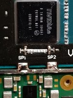
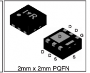
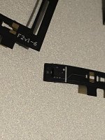
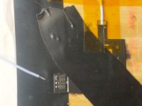
Here's my V2 flex cable secured to a piece of lumber with electrical tape and kapton to do the finer masking.
IMG_20230414_233349.jpg
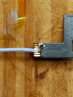
It tinned easily, and soldered easily without worrying about bridging to the side pins.
IMG_20230415_005810.jpg
Then I cleaned it, demasked it, and covered it in resin.
IMG_20230415_003221.jpg
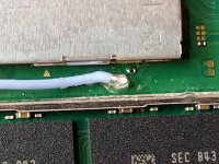
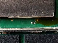
Here is the Lite's 3.3v points as called out by the definitive guide. I masked off the small component nearest them with Kapton, tinned the pads...
IMG_20230415_005113.jpg
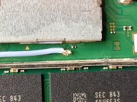
soldered my 30awg Kynar to it...
IMG_20230415_005642~2.jpg
and then also covered it in resin!
IMG_20230415_010421.jpg
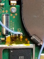
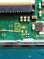
This is the GND point that has been masked off and soldered to.
IMG_20230415_012152.jpg
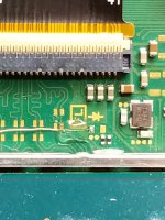
Here is the RST point (I opted for a single pad since I'm using 40awg magnet wire)
IMG_20230415_012655.jpg
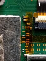
Here's that RST point covered in yet more resin
IMG_20230415_013722.jpg
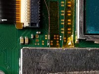
Masking off and tinning the DAT0 made things much simpler
IMG_20230415_014558.jpg
Here's CMD masked out and tinned
IMG_20230415_022127.jpg
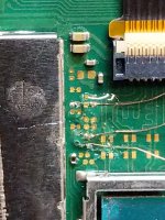
and here's DAT0, CMD, and CLK all soldered in and resin'd
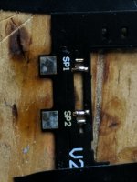
IMG_20230414_234727.jpg
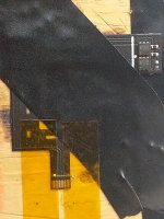
here's the flex pre-tinned
IMG_20230415_024925.jpg
This was one of my first attempts at soldering the flex (possibly the very first) but ultimately I got it all cleaned up and functioning properly.

So I learned that doing a switch lite is slightly more difficult than doing a full-size switch, but with the right approach it doesn't have to be impossible or terrifying.

Also, fun side-note, be very careful when trying to remove the battery connector on the switch lite, because you have to disturb a jumper cable that runs the front LCD. If any of these traces are interrupted, you will have to trace which ones have lost continuity and bridge the appropriate pins with magnet wire (ask me how I know)

The short and sweet of it, is that my household now has two hacked switches (which is a 100% success rate on 100% of the consoles in the house) and I feel more confident in my micro-soldering skills :D
 

FreeLander

Well-Known Member
Member
Joined
Apr 6, 2023
Messages
350
Trophies
0
Age
35
XP
467
Country
United States
My MOSFET order got stuck on AliExpress. I got no use for this V1 Cable. Will remove the MOSFET and install it on Lite. Any tips on removing it? Hot air? direct solder iron? and Am I to expect the same pinout as in here? Thanks
Post automatically merged:

I figured I would document my process of how I approached soldering in the tiny and tight areas of the switch lite, along with the close proximity of the pads to each other.

The main philosophy was "if it can be masked with Kapton during soldering, DO IT. Then flux it, solder it, clean it, and cover it in UV-cure resin."

This seemed to be pretty effective, and my only issues were this being my first flex install, I had to make sure I had good contact on the caps and no bridging.

View attachment 365360
Here's my V2 flex cable secured to a piece of lumber with electrical tape and kapton to do the finer masking.
View attachment 365361
It tinned easily, and soldered easily without worrying about bridging to the side pins.
View attachment 365366
Then I cleaned it, demasked it, and covered it in resin.
View attachment 365363
Here is the Lite's 3.3v points as called out by the definitive guide. I masked off the small component nearest them with Kapton, tinned the pads...
View attachment 365364
soldered my 30awg Kynar to it...
View attachment 365365
and then also covered it in resin!
View attachment 365367
This is the GND point that has been masked off and soldered to.
View attachment 365368
Here is the RST point (I opted for a single pad since I'm using 40awg magnet wire)
View attachment 365369
Here's that RST point covered in yet more resin
View attachment 365370
Masking off and tinning the DAT0 made things much simpler
View attachment 365371
Here's CMD masked out and tinned
View attachment 365372
and here's DAT0, CMD, and CLK all soldered in and resin'd
View attachment 365362
here's the flex pre-tinned
View attachment 365373
This was one of my first attempts at soldering the flex (possibly the very first) but ultimately I got it all cleaned up and functioning properly.

So I learned that doing a switch lite is slightly more difficult than doing a full-size switch, but with the right approach it doesn't have to be impossible or terrifying.

Also, fun side-note, be very careful when trying to remove the battery connector on the switch lite, because you have to disturb a jumper cable that runs the front LCD. If any of these traces are interrupted, you will have to trace which ones have lost continuity and bridge the appropriate pins with magnet wire (ask me how I know)

The short and sweet of it, is that my household now has two hacked switches (which is a 100% success rate on 100% of the consoles in the house) and I feel more confident in my micro-soldering skills :D
Taking your time and being extra cautious. I like that philosophy. I'm in a different situation where I have V1 cable and a Lite. Will try to remove the MOSFET and install it directly.
Post automatically merged:

If you're not in a hurry. I ordered this and it works fine for a tiny fraction of Amazon's Price.
 

Attachments

  • Screen Shot 2023-04-17 at 1.34.33 AM.png
    Screen Shot 2023-04-17 at 1.34.33 AM.png
    33.9 KB · Views: 57
  • IMG_6670.JPG
    IMG_6670.JPG
    1.5 MB · Views: 50
Last edited by FreeLander,

Phantomas77

Well-Known Member
Member
Joined
Dec 19, 2022
Messages
284
Trophies
0
XP
717
Country
Italy
My MOSFET order got stuck on AliExpress. I got no use for this V1 Cable. Will remove the MOSFET and install it on Lite. Any tips on removing it? Hot air? direct solder iron? and Am I to expect the same pinout as in here? Thanks
Post automatically merged:


Taking your time and being extra cautious. I like that philosophy. I'm in a different situation where I have V1 cable and a Lite. Will try to remove the MOSFET and install it directly.
Post automatically merged:


If you're not in a hurry. I ordered this and it works fine for a tiny fraction of Amazon's Price.
On OLED flex I had two NP2016DR. If that's a case for you, remove it with hot air and here you can find a datasheet (pins look to be in the same place).

EDIT: edited the link.
 
Last edited by Phantomas77,

FreeLander

Well-Known Member
Member
Joined
Apr 6, 2023
Messages
350
Trophies
0
Age
35
XP
467
Country
United States
On OLED flex I had two NP2016DR. If that's a case for you, remove it with hot air and here you can find a datasheet (pins look to be in the same place).
You rock! Thanks. The link you shared is for Sthetix's HATS install. I've seen that video. He didn't mention any MOSFETs, did he? Couldn't find any related links in the description too.
 

LogicalMadness

Well-Known Member
Member
Joined
Nov 3, 2014
Messages
287
Trophies
0
Age
41
XP
690
Country
United States
Hello, I just did an oled and when I activate the airplane mode, the joy with right does not work, what does that mean?

View attachment 365397

When you enable Airplane Mode, the controllers will not work wirelessly (unless you change settings FOR Airplane Mode).

If both JoyCons are physically connected to the tablet when you enable Airplane Mode, they should remain working. If they do not, check the rails' ribbon cables and associated connectors for issues.

Fully seated? Flux\residue\dirty? Torn?
*Edit: Connector flap not closed?
*Edit2: I'll bet it's that the ribbon isn't fully seated, the R-JC is harder to connect.
 
  • Love
Reactions: Dee87

jkyoho

Well-Known Member
Member
Joined
Sep 2, 2020
Messages
1,282
Trophies
0
Age
39
Location
TORONTO
Website
form.jotform.com
XP
2,210
Country
Canada

FreeLander

Well-Known Member
Member
Joined
Apr 6, 2023
Messages
350
Trophies
0
Age
35
XP
467
Country
United States
I've made now this file in scale Thickness of the Wires. just let the PDF in 100% scale.
Put AWG30, AWG36 and AWG40.
Mine looks like AWG40. I hope it helps some one else that don't know how it's in hand.
Man, everyone throws an AWG preference. I'm using 38AWG(0.1mm) enameled copper wire for all points, and 28AWG for 3v3. I'm going to try 38AWG on the MOSFET and I hope it works, although Raduis recommends a bit larger one (0.2mm), but those are hard to come by where I am.
 

detilmalala

Well-Known Member
Member
Joined
Mar 21, 2023
Messages
145
Trophies
0
Age
44
XP
202
Country
Uruguay
When you enable Airplane Mode, the controllers will not work wirelessly (unless you change settings FOR Airplane Mode).

If both JoyCons are physically connected to the tablet when you enable Airplane Mode, they should remain working. If they do not, check the rails' ribbon cables and associated connectors for issues.

Fully seated? Flux\residue\dirty? Torn?
*Edit: Connector flap not closed?
*Edit2: I'll bet it's that the ribbon isn't fully seated, the R-JC is harder to connect.
thanks
 
  • Like
Reactions: LogicalMadness

rsilveira1991

Active Member
Newcomer
Joined
Apr 16, 2023
Messages
29
Trophies
0
Age
33
XP
93
Country
Brazil
I didn't install any RP2040. Will arrive by these days.
I heard about that in PicoFLY we can't dothe Backup of the Nand. Is that true?
What's the bugs between PicoFLY and HWFLY?
 

Tom8823

Well-Known Member
Newcomer
Joined
Jun 22, 2020
Messages
53
Trophies
0
Age
36
XP
494
Country
Canada
Today I finally decided to try the mod and I ran into a first problem.

I decided to go with this approach as it's safer than soldering two wires to the cap and no matter what I do the solder won't stick to the ground pad (selected in circle). Is it covered in coating or something? I use flux but when I touch my iron tip to the point the solder will not attach to it at all.

1681693557457.png


Did you have to remove some sort of coating on this point @Dee87 ?

I'm also now afraid if I didn't fry this point because I tried first 290 celcius, then 320, then 350 and finally 380 and nothing.
The point looks a little bit discolored and when I try continuity test with multimeter between this point and ground it beeps 2/10 times so either there is a coating on it or i burned it.
 

lightninjay

Well-Known Member
Member
Joined
Mar 28, 2023
Messages
560
Trophies
0
Age
31
XP
1,374
Country
United States
Today I finally decided to try the mod and I ran into a first problem.

I decided to go with this approach as it's safer than soldering two wires to the cap and no matter what I do the solder won't stick to the ground pad (selected in circle). Is it covered in coating or something? I use flux but when I touch my iron tip to the point the solder will not attach to it at all.

View attachment 365430

Did you have to remove some sort of coating on this point @Dee87 ?

I'm also now afraid if I didn't fry this point because I tried first 290 celcius, then 320, then 350 and finally 380 and nothing.
The point looks a little bit discolored and when I try continuity test with multimeter between this point and ground it beeps 2/10 times so either there is a coating on it or i burned it.
So one notoriously difficult thing about Ground (which that point is a part of) is that by nature it is connected to all other ground points, and is therefor the first candidate as a passive heatsink. Heatsinks are designed to dissipate heat, so to solder to the ground plane, you have to be at a decently high temperature. Clean the spot with some iso, turn your iron to about 390, tin your iron, flux the spot, and then go in to get the pad shiny. It can take a few seconds since it's attached to ground but still a tiny point.
 

Dee87

Well-Known Member
Member
Joined
Mar 19, 2023
Messages
1,139
Trophies
1
XP
1,577
Country
Germany
Today I finally decided to try the mod and I ran into a first problem.

I decided to go with this approach as it's safer than soldering two wires to the cap and no matter what I do the solder won't stick to the ground pad (selected in circle). Is it covered in coating or something? I use flux but when I touch my iron tip to the point the solder will not attach to it at all.

View attachment 365430

Did you have to remove some sort of coating on this point @Dee87 ?

I'm also now afraid if I didn't fry this point because I tried first 290 celcius, then 320, then 350 and finally 380 and nothing.
The point looks a little bit discolored and when I try continuity test with multimeter between this point and ground it beeps 2/10 times so either there is a coating on it or i burned it.
Yeah its pretty hard to get it to stick there , u can also just take it from the shield . u need to heat it good to get it to connection
Post automatically merged:

So one notoriously difficult thing about Ground (which that point is a part of) is that by nature it is connected to all other ground points, and is therefor the first candidate as a passive heatsink. Heatsinks are designed to dissipate heat, so to solder to the ground plane, you have to be at a decently high temperature. Clean the spot with some iso, turn your iron to about 390, tin your iron, flux the spot, and then go in to get the pad shiny. It can take a few seconds since it's attached to ground but still a tiny point.
This Boi is on fire Today :grog:
 

RecklessElectronics

Member
Newcomer
Joined
Apr 10, 2023
Messages
12
Trophies
0
Age
36
XP
64
Country
United States
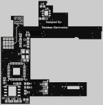
Not sure if anyone else has produced a design that is quick to solder on and nests inside the switch easier yet. I just finished this one today and it is intended to be a flexible PCB. It is just a prototype and will need some adjustments I'm sure, but I mapped the GPIOs the same as the original Waveshare board so I believe the original firmware will flash to this with no issue.

EDIT: I forgot to include that this is for the Lite. I don't have any other units to measure but once I verify functionality I would be willing to adapt the design and/or post the files needed to modify to fit other units.

Anyone interested in this thing?
 

Attachments

  • Reckless_PicoFly_Back.jpg
    Reckless_PicoFly_Back.jpg
    86.1 KB · Views: 53
  • Reckless_PicoFly_Front.jpg
    Reckless_PicoFly_Front.jpg
    72.5 KB · Views: 52
Last edited by RecklessElectronics,

Dee87

Well-Known Member
Member
Joined
Mar 19, 2023
Messages
1,139
Trophies
1
XP
1,577
Country
Germany
Not sure if anyone else has produced a design that is quick to solder on and nests inside the switch easier yet. I just finished this one today and it is intended to be a flexible PCB. It is just a prototype and will need some adjustments I'm sure, but I mapped the GPIOs the same as the original Waveshare board so I believe the original firmware will flash to this with no issue.

Anyone interested in this thing?
Woooow now this is awesome .
Beautiful job !!!

Is this gone be open source or for sale?

I'm Very interested , hit me up
 

Site & Scene News

Popular threads in this forum

General chit-chat
Help Users
    SylverReZ @ SylverReZ: @K3Nv2, Bad dragon