Hacking Hardware Picofly - a HWFLY switch modchip

Dee87

Well-Known Member
Member
Joined
Mar 19, 2023
Messages
1,139
Trophies
1
XP
1,589
Country
Germany
I finally got my hands on the Zelda Oled that I ordered 3 months ago and I decided to try and set a proper dat0 by removing the emmc.

A couple of things to point out:
- It was easier than I thought but I've been preparing/practicing this for quite some time so for anyone reading this I would suggest you do your homework before diving in.
- The amount of beating these chips can handle is quite impressive.
- Same as Takezo-San wrote a couple of post above, I had no luck with stencil and paste (maybe I was stressed and tired because I started doing this at 11pm) so after trying a couple of times and failed I just did it manually one by one with 0.3 balls.
Everything went smoothly afterwards and since the board was already off I also decided to try the abal's mosfet placement on the back of the apu.
I just want to say that this is an amazing thread with some amazing people and the list of people to say thank you is way too long but I have to point out @Dee87 and @Takezo-San without whom I probably would have not had the courage/will to go through with this process and a special thanks to @abal1000x who’s dedication and contribution to this whole mod is priceless.
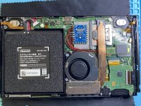
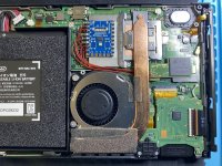
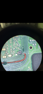
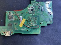
Below you can see some pictures, I should have done more but I got carried away in the heat of the moment :D


Nice looking good :-)

What was ur issue with the stencil?

U have to put magnet or something around the emmc so the rest of the stencil is laying on something so it doesn't have that much chance of bending.

Then add ur solder paste , if u have enough set ur tweezers in the middle of the stencil and push it on the emmc.

Then set ur hot air at 180 a bit more then ur pastes melting point and slowly best ur stencil up don't go straight to the stencil so its not a heat schock otherwise it Gonna bend really fast due to the heat.
Wait till everything is melted but always keep pressure on the middle of the stencil.

After that I usually add a bit flux heat it up one more time and then take the stencil off
 
  • Like
Reactions: QuiTim

Takezo-San

Well-Known Member
Member
Joined
May 3, 2023
Messages
261
Trophies
0
Age
39
XP
349
Country
Seychelles
Congratulations! But it will take you very long time to finish and it is not an efficient way.
I see many people go the reballing way and at least i want to help giving some info for those having a hard time.

Here are some of the most important tips that you must use while reballing a chip using a stencil:

First of all use flux on chip and mix leaded solder on the no lead balls and place the stencil over the chip.

Take some ammount of low melt soldering paste with your spudger and press it 4-5 times on the paper towel to remove as much flux as you can from the soldering paste. This is extremely helpful for newcomers as it will minimize bubbling of the soldering paste during the reballing procedure.

Use the spudger to apply the soldering paste over the stencil multiple times to fill very well the holes and clean the excess soldering paste also very well. Use you tweezers to press down the stencil above and bellow the emmc.Give it a good amount of pressure! This is extremely important especially on low quality stencils. 3d stencils are the best because they are thicker and they do not tend to bend easily! Cheap stencils are not thick and they bend very quickly and this is the main reason that soldering balls under the chip are getting mixed up!

If you use quick 861dw which is one of the most used hot air stations worldwide use 335 and 12 airflow. Temps and airflows vary from station to station so you must find your unique sweet spot. The main idea though is slow airflow moderate temp. You need higher temp than normal because you have very little airlow. Keep pressing down using your tweezers as metioned above! Start from the bottom left very slowly forming the balls to the top right. When done lift your tweezers.

Remove the stencil with the help of some isopropil alcohol if needed, add some flux on the balls and do a reflow.

If you do these steps i guarantee you that you will have success every single time, first try!

Little pressure of the stencil, bubbling of soldering paste and high air flows are the three main reasons of failed reballings.

Reballings can be done with very cheap stencils and very cheap hot air stations and without any of these tips i mentioned above if you have the right experience!!
But if you try these stuff for the first time use these tips and you will be fine!
Where does one attain a 3d printed heat resistant stencil for bga153? Thanks for the tips.
 

snaker

Well-Known Member
Member
Joined
Mar 30, 2009
Messages
217
Trophies
1
Website
biohazard-era.blogspot.com
XP
696
Country
United States
Where does one attain a 3d printed heat resistant stencil for bga153? Thanks for the tips.
This claims to be a 3d stencil for different emmc chips. But it has happened to me in the past to be a simple stencil.
But in this case it is qianli brand. So for sure it will be good quality even if it may not be 3d.
https://www.aliexpress.com/item/100....order_list.order_list_main.99.21ef1802jHv2nv

For example these gold ones are for sure 3d stencils. I have used them a lot on different iphone models and they are excellent but i cant find them for bga153

https://www.aliexpress.com/item/33002353235.html?spm=a2g0o.productlist.main.27.1f746b13V4L60H&algo_pvid=60cded61-51ff-4db9-8613-4bc810d64db6&algo_exp_id=60cded61-51ff-4db9-8613-4bc810d64db6-13&pdp_npi=4@dis!EUR!16.06!12.85!!!17.25!!@2101f49c16919505541352885e4c6e!10000006037776668!sea!GR!129211643!&curPageLogUid=dEOYfkbsWx1L
 
  • Like
Reactions: Takezo-San

FXDX

Well-Known Member
Member
Joined
Sep 15, 2019
Messages
325
Trophies
0
XP
2,001
Country
Dominican Republic
Picofly soldered on V2 with mosfet on the back pcb. Excellent glitch time.
 

Attachments

  • 2023_08_13_12_03_IMG_1941.JPG
    2023_08_13_12_03_IMG_1941.JPG
    2.4 MB · Views: 29
  • 2023_08_13_12_03_IMG_1942.JPG
    2023_08_13_12_03_IMG_1942.JPG
    2.2 MB · Views: 28
  • 2023_08_13_14_20_IMG_1946.PNG
    2023_08_13_14_20_IMG_1946.PNG
    3.3 MB · Views: 30
  • 2023_08_13_10_23_IMG_1938.JPG
    2023_08_13_10_23_IMG_1938.JPG
    2.3 MB · Views: 31

FreeLander

Well-Known Member
Member
Joined
Apr 6, 2023
Messages
350
Trophies
0
Age
35
XP
467
Country
United States
Hello, I'd like your input on this, guys.
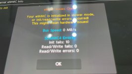
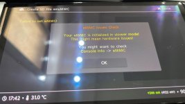
Picofly installed nicely on OLED and worked fine for a week. Now I get "eMMC slow mode" but not on the main hekate screen but when I create eMMUC.
Furthermore, eMMC tab shows the error with 0 bus speed.
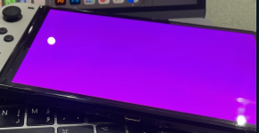
OFW > purple screen.
CFW > failed to init eMMC, failed launch HOS

Do you guys think this is fixable with adding resistors on Dat0,CMD?, or is it a CMD resistor issue?, or eMMC?
 

Attachments

  • PHOTO-2023-08-14-18-30-22.jpg
    PHOTO-2023-08-14-18-30-22.jpg
    53.8 KB · Views: 29
  • PHOTO-2023-08-14-17-42-02.jpg
    PHOTO-2023-08-14-17-42-02.jpg
    74.1 KB · Views: 23
  • Screenshot 2023-08-14 at 8.07.34 PM.png
    Screenshot 2023-08-14 at 8.07.34 PM.png
    566.1 KB · Views: 31

snaker

Well-Known Member
Member
Joined
Mar 30, 2009
Messages
217
Trophies
1
Website
biohazard-era.blogspot.com
XP
696
Country
United States
Hello, I'd like your input on this, guys.
Picofly installed nicely on OLED and worked fine for a week. Now I get "eMMC slow mode" but not on the main hekate screen but when I create eMMUC.
Furthermore, eMMC tab shows the error with 0 bus speed.
OFW > purple screen.
CFW > failed to init eMMC, failed launch HOS

Do you guys think this is fixable with adding resistors on Dat0,CMD?, or is it a CMD resistor issue?, or eMMC?
Did you used a dat0 adapter?
 
  • Like
Reactions: Switxh

FreeLander

Well-Known Member
Member
Joined
Apr 6, 2023
Messages
350
Trophies
0
Age
35
XP
467
Country
United States
There is a very high probablity that the adapter did not installed correctly or it was not high quality, bridged the dat0 with dat1 and corrupted your emmc. What adapter did you used?
The new V5 version. Used it on 20+ OLEDs with no issues. The one that has good half circle. This is news to me since I always push my adaptors to the right to avoid dat1.

Any idea if this can be fixed?
 

Dee87

Well-Known Member
Member
Joined
Mar 19, 2023
Messages
1,139
Trophies
1
XP
1,589
Country
Germany
Hello, I'd like your input on this, guys.
Picofly installed nicely on OLED and worked fine for a week. Now I get "eMMC slow mode" but not on the main hekate screen but when I create eMMUC.
Furthermore, eMMC tab shows the error with 0 bus speed.
OFW > purple screen.
CFW > failed to init eMMC, failed launch HOS

Do you guys think this is fixable with adding resistors on Dat0,CMD?, or is it a CMD resistor issue?, or eMMC?
i would also say this is caused by a dat0 adapter, eather not properly set and it moved or it bent while it got warm what the issue is with some dat0 Adapter.

some how it bridged and not thats the reason u have this issue.

but since u have it already installed for a week u should have made a backup. so take the emmc out set it properly and restore the emmc and ur issue should be gone
 

WorfRB

Active Member
Newcomer
Joined
Jun 6, 2016
Messages
28
Trophies
0
Age
43
XP
963
Country
Italy
For now I'm installing picofly on v1/v2 and lite switches without any issues.

What's the best strategy for the oleds if you want to make a first perfect install? Reball from start the emmc with fresh leaded solder balls and then install the dat0 adapter?
 

Dee87

Well-Known Member
Member
Joined
Mar 19, 2023
Messages
1,139
Trophies
1
XP
1,589
Country
Germany
For now I'm installing picofly on v1/v2 and lite switches without any issues.

What's the best strategy for the oleds if you want to make a first perfect install? Reball from start the emmc with fresh leaded solder balls and then install the dat0 adapter?
I would go with reballing and setting a permanent dat0 Adapter with repair pads.
leave the dat0 adapter away and be done with it ,that how i only installd oleds without any issues
 
  • Like
Reactions: WorfRB

Switxh

Well-Known Member
Member
Joined
Mar 11, 2023
Messages
110
Trophies
0
Age
28
XP
273
Country
United Kingdom
For now I'm installing picofly on v1/v2 and lite switches without any issues.

What's the best strategy for the oleds if you want to make a first perfect install? Reball from start the emmc with fresh leaded solder balls and then install the dat0 adapter?
Why would you reball the EMMC if you're just going to install a dat0 adapter lol. You reball it so you DON'T use those adapters...
 
  • Like
Reactions: Dee87

WorfRB

Active Member
Newcomer
Joined
Jun 6, 2016
Messages
28
Trophies
0
Age
43
XP
963
Country
Italy
I would go with reballing and setting a permanent dat0 Adapter with repair pads.
leave the dat0 adapter away and be done with it ,that how i only installd oleds without any issues
Repair pads? You mean solder lugs used for iphones or connectors with ripped pads/traces?
 

WorfRB

Active Member
Newcomer
Joined
Jun 6, 2016
Messages
28
Trophies
0
Age
43
XP
963
Country
Italy
Why would you reball the EMMC if you're just going to install a dat0 adapter lol. You reball it so you DON'T use those adapters...
I thought that these emmc fails are due to the lead-free solder balls they're using. So basically just put a wire under the dat0 ball and should be fine, right?
 

Switxh

Well-Known Member
Member
Joined
Mar 11, 2023
Messages
110
Trophies
0
Age
28
XP
273
Country
United Kingdom
I thought that these emmc fails are due to the lead-free solder balls they're using. So basically just put a wire under the dat0 ball and should be fine, right?
No there's nothing wrong with their use of lead-free solder. You probably heard what Sthetix said about reFLOWING the EMMC which I won't get into it but basically no one does that now anyway so you don't need to be worrying about the type of solder they used in the factory.

To do the job in a way that is most reliable and will last the longest you need to remove the EMMC and install a permanent dat0 line to the pad on the board. Then you reBALL the EMMC with fresh solder and reinstall it. I use trace repair lugs personally. But I have seen people flatten 0.1mm wire and use that for the permanent dat0 line. But to reiterate, you have to remove the EMMC and reball it to use this method.
 
  • Like
Reactions: WorfRB

WorfRB

Active Member
Newcomer
Joined
Jun 6, 2016
Messages
28
Trophies
0
Age
43
XP
963
Country
Italy
Ok thanks, I got it, Basically it's the same job when you do pad repair on the usb-c connector ,you fix the wires/solder lugs with uv mask to avoid them moving, and then place on top the component.
 
  • Like
Reactions: Switxh

Site & Scene News

Popular threads in this forum

General chit-chat
Help Users
  • No one is chatting at the moment.
    denpafan @ denpafan: swag