Hacking Hardware Picofly - a HWFLY switch modchip

AntonIX

Active Member
Newcomer
Joined
Jan 14, 2023
Messages
34
Trophies
0
Age
24
Website
devpins.org
XP
217
Country
Russia
Thanks to everyone who helped me and especially rehius for his awesome firmware!
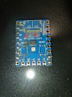
Now I had to put everything back. I have two picos. One unbroken with buttons and usb and one cleared but without a few resistors. Anyone know their capacity?
 

Attachments

  • photo_2023-04-14_23-25-26.jpg
    photo_2023-04-14_23-25-26.jpg
    385.3 KB · Views: 67

trippy86

Well-Known Member
Newcomer
Joined
Aug 17, 2017
Messages
72
Trophies
0
Age
38
XP
142
Country
United Kingdom
G
I've got a switch and switch lite to do tomorrow, ive got the ribbon cables for both.

I see some users removing the usb connector and buttons and some not, is it necessary to remove them

Also what's the best guide or tutorial to use?

Thx all
 

AntonIX

Active Member
Newcomer
Joined
Jan 14, 2023
Messages
34
Trophies
0
Age
24
Website
devpins.org
XP
217
Country
Russia
G
I've got a switch and switch lite to do tomorrow, ive got the ribbon cables for both.

I see some users removing the usb connector and buttons and some not, is it necessary to remove them

Also what's the best guide or tutorial to use?

Thx all
You have to remove them to fit rp2040 to your switch.
 

lightninjay

Well-Known Member
Member
Joined
Mar 28, 2023
Messages
560
Trophies
0
Age
31
XP
1,383
Country
United States
G
I've got a switch and switch lite to do tomorrow, ive got the ribbon cables for both.

I see some users removing the usb connector and buttons and some not, is it necessary to remove them

Also what's the best guide or tutorial to use?

Thx all
https://gbatemp.net/download/a-definitive-picofly-install-guide.37968/

There's a guide that I wrote up and posted two days ago. Removing the USB and buttons is not NECESSARY, but it definitely makes the back cover fit better.
 

Dee87

Well-Known Member
Member
Joined
Mar 19, 2023
Messages
1,139
Trophies
1
XP
1,578
Country
Germany
G
I've got a switch and switch lite to do tomorrow, ive got the ribbon cables for both.

I see some users removing the usb connector and buttons and some not, is it necessary to remove them

Also what's the best guide or tutorial to use?

Thx all
but only remove them after u succesfully tested them switch with a 2.6+ firmware otherwise if u have issues u will have to resolder
Post automatically merged:

here is an update pinout and cutting guide for the raspi pico
have fun
pico cut2.jpg
 

AlanPavlish

Member
Newcomer
Joined
Apr 14, 2023
Messages
9
Trophies
0
Age
44
XP
50
Country
Serbia, Republic of
Thanks to everyone who helped me and especially rehius for his awesome firmware!
Now I had to put everything back. I have two picos. One unbroken with buttons and usb and one cleared but without a few resistors. Anyone know their capacity?
I just measured with my multimeter.
Left one 0.998k
Right one is a capacitor. And I am not sure how to measure it.
 
Last edited by AlanPavlish,
  • Like
Reactions: AntonIX

trippy86

Well-Known Member
Newcomer
Joined
Aug 17, 2017
Messages
72
Trophies
0
Age
38
XP
142
Country
United Kingdom
https://gbatemp.net/download/a-definitive-picofly-install-guide.37968/

There's a guide that I wrote up and posted two days ago. Removing the USB and buttons is not NECESSARY, but it definitely makes the back cover fit better.
Thx for that

but only remove them after u succesfully tested them switch with a 2.6+ firmware otherwise if u have issues u will have to resolder
Post automatically merged:

here is an update pinout and cutting guide for the raspi pico
have fun
View attachment 364980
Oh God cutting up a pico surely easier just to use a 2040 zero

Thx all
 
  • Like
Reactions: LogicalMadness

AlanPavlish

Member
Newcomer
Joined
Apr 14, 2023
Messages
9
Trophies
0
Age
44
XP
50
Country
Serbia, Republic of
Thanks to everyone who helped me and especially rehius for his awesome firmware!
Now I had to put everything back. I have two picos. One unbroken with buttons and usb and one cleared but without a few resistors. Anyone know their capacity?
Please check my updated post. Sorry. Multimeter was showing different values, and while examining with magnifier, I realised on the left side there is nothing :)
 
  • Haha
Reactions: AntonIX

rehius

Well-Known Member
Member
Joined
Feb 6, 2023
Messages
377
Trophies
1
Age
34
XP
1,790
Country
Canada
Also guys, been researching for the past 2 months, somehow i already got the gist, but what are the particular specific issues or notes i should know about? like...

-RST point is very sensitive so make sure to clean it properly without flux leaving behind and covering some tape...

-Adding additional resistors if it doesnt work...

-20k resistor for RST if it does not work..

anymore?
The mosfet -> APU soldering must be as good as possible, to reduce resistance and improve glitching. So 0.2mm diameter wires, good flux, low temp soldering paste pre-applied onto the caps

20k is not working anymore, that was for 1.x fw only

there are some consoles in the wild that give glitch error (cyan LED) but work fine after pressing reset on the rp2040, hopefully that will be fixed

no resistors on the eMMC lines can lead to data corruption

single mosfet is enough, it is 76A capable. but it's better to connect it to both capacitors

you can fit rp2040-zero without desoldering parts, but you must cut the cover then

in total now 5 boards are supported (ws2040-zero/one, xiao2040, itsybitsy, RP Pico), the waveshare is a default one, for others you must bridge detection pins

Unpatched v1 also works, but people keep asking that

with really low battery you can see the IPL screen, but further load may fail

putting .uf2 firmware file over USB is enough, no need to erase or reset it in any way

update through the toolbox is safe (unless there is a critical bug in the new firmware you are writing). it completes only after a successful boot with the new firmware. otherwise the old firmware starts on the next boot.

picofly automatically resets (and reflashes sdloader into the BOOT0) in case of system update detected, multiple unsuccessful boots, pico firmware update, and even putting into different console.

purple LED might be also caused by bad RST connection

long thin CMD/CLK/D0 wires may also cause "slow eMMC mode" and data corruption

despite of detection pins, all possible mosfet gate pins (6, 22, 15, 24) are pulled down to prevent accidental CPU burn by the high current

there is a possibility of unsupported eMMC, for example, it has never been tested on Micron ones

rp2040 consumes a bit of power after the glitch, now it's 0.6 mA, can't go lower, hardware limits.
 

Frank975

New Member
Newbie
Joined
Apr 9, 2023
Messages
2
Trophies
0
Age
48
XP
29
Country
Italy
Hello everyone I have a problem with my switch....... I had a rp2040 zero mounted but after some hard boot problems in sysnand I decided to remove it and put an sx core that I had... Now the console has a boot very long and when it goes to sleep it freezes...... Can someone help me?
 

lightninjay

Well-Known Member
Member
Joined
Mar 28, 2023
Messages
560
Trophies
0
Age
31
XP
1,383
Country
United States
MOSFETs are very small.
Soldering S points together will transfer heat to all of them.
It is extremely difficult to solder to the G point beside the S point.
You could also try adapting your soldering iron to a smaller tip like this guy does. When doing crafty things, you must attempt to be craftier than the craft you wish to be crafting, savvy?
This guy has a pretty clever technique for adapting a blunt soldering iron to doing micro-soldering


zehu

New Member
Newbie
Joined
Apr 14, 2023
Messages
2
Trophies
0
Age
40
XP
40
Country
Spain
hello everyone, sorry for my english.
I have a few doubts.
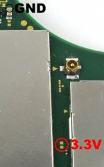
I have a lite, the picofly uses the same points as hwfly, because I have seen in the images that you don't get the 3.3v from the same place or is it an alternative point and if so, should it be bridged?
20230413_195527.jpg

another would be that in the capture of hwfly a point is used but in yours you mark two points with a circle that must be joined or choose one of the two?
20230413_195455.jpg
 

Attachments

  • 20230413_195527.jpg
    20230413_195527.jpg
    355.6 KB · Views: 50
  • 20230413_195455.jpg
    20230413_195455.jpg
    201.5 KB · Views: 52

Marcelo437

New Member
Newbie
Joined
Apr 15, 2023
Messages
3
Trophies
0
Age
42
XP
103
Country
Bolivia
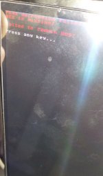
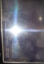
hello, why does that error happen, help me please
 

Attachments

  • 20230414_185938.jpg
    20230414_185938.jpg
    2.3 MB · Views: 50
  • 20230414_190648.jpg
    20230414_190648.jpg
    1.6 MB · Views: 62

lightninjay

Well-Known Member
Member
Joined
Mar 28, 2023
Messages
560
Trophies
0
Age
31
XP
1,383
Country
United States
hello everyone, sorry for my english.
I have a few doubts.
I have a lite, the picofly uses the same points as hwfly, because I have seen in the images that you don't get the 3.3v from the same place or is it an alternative point and if so, should it be bridged?
View attachment 365009
another would be that in the capture of hwfly a point is used but in yours you mark two points with a circle that must be joined or choose one of the two?
View attachment 365010
The reality of any circle that has two points in it, is that BOTH points are viable. It is up to choice, whether you want to put your wire to one pad, or to both. This is because when analyzing the board traces, it can be seen that the pads are in fact inline on the same trace.
Post automatically merged:

hello, why does that error happen, help me please
I would bet money that you flashed the 2.5 + unlock .uf2, didn't you...
 
  • Like
Reactions: LogicalMadness

ppeach

Well-Known Member
Newcomer
Joined
Mar 13, 2023
Messages
63
Trophies
0
XP
209
Country
Zimbabwe
well then u dont have the right tools
i guess the best for u would be to order v1/v2 flex cables
The proper tools are already in use ...
The rest is a matter of my technique.
Using flex cable for the first installation was the right choice.
This is more difficult than soldering to test points on the board.
 

Site & Scene News

Popular threads in this forum

General chit-chat
Help Users
  • K3Nv2 @ K3Nv2:
    Thanks for signing up at LinusTechTips
  • QuarterCut @ QuarterCut:
    holey shmoley!
  • BigOnYa @ BigOnYa:
    Your credit card has been charged. Thank you.
  • K3Nv2 @ K3Nv2:
    Your screwdriverPlus will arrive in three weeks
    +1
  • QuarterCut @ QuarterCut:
    K64_Waddle_Dee_Artwork_1.jpg

    my reaction to such information
    +2
  • BigOnYa @ BigOnYa:
    Press 1 for English. Press 2 for Pig Latin. Or press 3 to speak to a representative.
  • BakerMan @ BakerMan:
    guys, i need help, i got into an argument about what genre radioactive is, and i forgot who made it
  • Sicklyboy @ Sicklyboy:
    @BakerMan, Imagine Dragons
  • Sicklyboy @ Sicklyboy:
    Dragon deez nuts across yo face GOTEEM
  • Sicklyboy @ Sicklyboy:
    lmao now I realize that was probably the joke in the first place
    +1
  • BakerMan @ BakerMan:
    IMAGINE DRAGON DEEZ NUTS ACROSS YO- FUCK HE BEAT ME TO IT
  • BigOnYa @ BigOnYa:
    You have selected 4 - Death by Snu Snu, please stand by...
    +1
  • BakerMan @ BakerMan:
    lucky bastard
    +1
  • Sicklyboy @ Sicklyboy:
    hahahaha I'm half way through a bag off my Volcano and my tolerance is way down because I haven't been smoking much lately, so I was a little slow to catch that that was what your angle was 🤣🤣
    +1
  • Sicklyboy @ Sicklyboy:
    Also I was just excited to know a music reference for once (I am the LAST person in the world that you want on your trivia team)
    +2
  • K3Nv2 @ K3Nv2:
    Bummer webos 7.4 isnt working with dejavuln-autoroot
  • Sicklyboy @ Sicklyboy:
    PS4 right? I think that's what mine's on. Or 5.6, maybe.
  • K3Nv2 @ K3Nv2:
    [!] Installation failed (devmode_enabled not recognized)
  • K3Nv2 @ K3Nv2:
    0.5 seemed to work whatever lol i wont bitch
    K3Nv2 @ K3Nv2: 0.5 seemed to work whatever lol i wont bitch