HWFLY chips will brick your OLED. Here is how to avoid it

First things first, I should start by saying that if you have an OLED-specific clone chip you're fine.

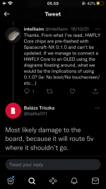
Anyways, all HWFLY Lite chips come with Spacecraft v1. For those that don't know, Spacecraft v1 sets certain pins to 5V that shouldn't be set to that on an OLED.

You can find more info in the readme of my application here: https://github.com/Pheeeeenom/payloadchecker

All this application does is check the payload that's currently written and checks it to verified hashes stored in the program.

Steps to follow are:

Boot hekate
Dump BOOT0
Check it on application

If you have a genuine modchip, update it to the latest Spacecraft v2 before you install it into an OLED.

The OLED-specific modchip also comes with broken USB debugging, if you want to fix this issue you will need to write this repaired firmware binary.
 

Tembokbesi

Member
Newcomer
Joined
Aug 14, 2021
Messages
18
Trophies
0
Age
34
XP
89
Country
Indonesia
Excuse me.... Do any of you guys have the Electronic diagram of the SX core or hwfly??? Cause I have and I' mm in electronics for more then 20 years and repairing since 12. Any low level electronicien would say that both ICE40 & GD32 chip are volted with 3,3v , there is no way these chips could output any upper voltage then the max power voltage. There input voltages are 3,3 from emmc, regulated to 1,8 - 2,5 & 1,2 . Nothing else. This complete BS, sorry to say. To have anything more then 3,3v you would need a higher voltage to go into the chip circuit and there is not! Only 5v going in is from the reprogramming USB cable when you connect this to a USB port. Gpio high or low means it will take the max voltage of the chip or gnd. Chip cannot output 5v when receiving a max voltage of 3,3v. If anything in can passthru the voltage existing from the motherboard but not increase it, neither the programming code or the chip itself can give me. And just so you know I'm a specialist on fpga and got a diploma in vhdl & verilog coding. I've done the xbox360 chips from scratch with Gligli (the one that released all the initale reset glitch on Xbox), I made my own chips and coding for these chips and I was the one to explain how to hack the new motherboard xbox360 corona working with the new emmc system.
It make sense.. i think the hardware (hwfly chip) is not cappability to output 5v so it will be fine 😁
 
  • Like
Reactions: zakwarrior

james194zt2

Well-Known Member
Newcomer
Joined
Jan 4, 2022
Messages
57
Trophies
0
Age
42
XP
165
Country
United Kingdom
Makes sense, I am still trying to find out why mine is draining the battery so much, even when it is in OFW my battery drain is about 8-10% an hour in standby on a 1 month old switch! The switch is even slightly warm on the back in standby so I am wondering if there is something wrong with my HWFly.
 

zakwarrior

Well-Known Member
Newcomer
Joined
Feb 20, 2016
Messages
60
Trophies
0
Age
39
XP
262
Country
France
Sorry to say but this was just a big mistake made by someone (probably trying to help) but doesn't know the basics of electronics. And for the future before making a panic on everyone (got a bunch of mails and calls of people reacting to this 5v story today...), please make sure you know what you're talking about, no offense bro. I'm sure you tried to do good.
 
  • Like
Reactions: Tembokbesi

Mena

Well-Known Member
OP
Member
Joined
Oct 5, 2020
Messages
148
Trophies
0
Age
29
XP
1,032
Country
United States
Excuse me.... Do any of you guys have the Electronic diagram of the SX core or hwfly??? Cause I have and I' mm in electronics for more then 20 years and repairing since 12. Any low level electronicien would say that both ICE40 & GD32 chip are volted with 3,3v , there is no way these chips could output any upper voltage then the max power voltage. There input voltages are 3,3 from emmc, regulated to 1,8 - 2,5 & 1,2 . Nothing else. This complete BS, sorry to say. To have anything more then 3,3v you would need a higher voltage to go into the chip circuit and there is not! Only 5v going in is from the reprogramming USB cable when you connect this to a USB port. Gpio high or low means it will take the max voltage of the chip or gnd. Chip cannot output 5v when receiving a max voltage of 3,3v. If anything in can passthru the voltage existing from the motherboard but not increase it, neither the programming code or the chip itself can give this. And just so you know I'm a specialist on fpga and got a diploma in vhdl & verilog coding. I've done the xbox360 chips from scratch with Gligli (the one that released all the initale reset glitch on Xbox), I made my own chips and coding for these chips and I was the one to explain how to hack the new motherboard xbox360 corona working with the new emmc system. All this to say that i know my sh#t

Fellow electrical engineer chiming in here. 5V hasn't been used in microcontrollers neither as a supply voltage nor for any logic busses in about two decades. Not saying this absolutely has to be complete BS but I'd be surprised if this actually turns out to be legit.
Especially the claim in the original post that OP has already seen a lot of dead OLED Switches because of this seems weird to me. First, I don't think there even are "a lot" of modded Aulas out there, yet, and secondly, even if this modchip would supply 5v to some pins that are only supposed to receive 3.3v I would be surprised if that would actually cause any issues before half a year of usage or something.

I do a lot of Game Boy modding and this 3.3 vs. 5 Volts topic is discussed there as well. For example, the Game Boy and Game Boy Color still use 5V everywhere, the GB being released in the 1980s and the GBC in the 1990s. The Game Boy Advance, however, already uses controllers that operate on 3.3 V (except if it is working in GB(C) mode).
There are some Chinese flashcards which use 3.3V even on the GB and GBC because it's hard to find microcontrollers that are still using 5V and designing the cards with level shifters to "convert" the voltage from 5 V to 3.3 V vice versa would mean increased production cost. It is commonly accepted that using these flashcards will damage your Game Boy and flashcard over time because the voltages essentially don't match, however, people are still using them and there doesn't seem to be a huge influx of broken devices because of that.
Sorry to rain on both of your parades, this has nothing to do with the chip outputting 5V...If either of you read the readme on my application you would have seen that it's power management setup based on the PAYLOAD that is written to your eMMC.

The following code that is compiled into THE PAYLOAD THAT IS WRITTEN TO THE EMMC, contains the following

Code:
 if (mariko)
    {
        uint8_t val = 0x3A;
        i2c_send(I2C_5, MAX77620_PWR_I2C_ADDR, MAX77620_REG_SD2, &val, 1);
        val = 0x71;
        i2c_send(I2C_5, MAX77620_PWR_I2C_ADDR, MAX77620_REG_SD2_CFG, &val, 1);
        val = 0xD0;
        i2c_send(I2C_5, MAX77620_PWR_I2C_ADDR, MAX77620_REG_LDO0_CFG, &val, 1);
    }
    else
    {
        uint8_t val = 0xD0;
        i2c_send(I2C_5, MAX77620_PWR_I2C_ADDR, MAX77620_REG_LDO0_CFG, &val, 1);
        val = 0x09;
        i2c_send(I2C_5, MAX77620_PWR_I2C_ADDR, MAX77620_REG_GPIO7, &val, 1);
    }
    
    /* Enable MIPI CAL, DSI, DISP1, HOST1X, UART_FST_MIPI_CAL, DSIA LP clocks. */
    car->rst_dev_h_clr = 0x1010000;
    car->clk_enb_h_set = 0x1010000;
    car->rst_dev_l_clr = 0x18000000;
    car->clk_enb_l_set = 0x18000000;
    car->clk_enb_x_set = 0x20000;
    car->clk_source_uart_fst_mipi_cal = 0xA;
    car->clk_enb_w_set = 0x80000;
    car->clk_source_dsia_lp = 0xA;
    /* DPD idle. */
    pmc->io_dpd_req = 0x40000000;
    pmc->io_dpd2_req = 0x40000000;
    /* Configure pins. */
    pinmux->nfc_en &= ~PINMUX_TRISTATE;
    pinmux->nfc_int &= ~PINMUX_TRISTATE;
    pinmux->lcd_bl_pwm &= ~PINMUX_TRISTATE;
    pinmux->lcd_bl_en &= ~PINMUX_TRISTATE;
    pinmux->lcd_rst &= ~PINMUX_TRISTATE;

    /* Configure Backlight +-5V GPIOs. */
    gpio_configure_mode(GPIO_LCD_BL_P5V, GPIO_MODE_GPIO);
    gpio_configure_mode(GPIO_LCD_BL_N5V, GPIO_MODE_GPIO);
    gpio_configure_direction(GPIO_LCD_BL_P5V, GPIO_DIRECTION_OUTPUT);
    gpio_configure_direction(GPIO_LCD_BL_N5V, GPIO_DIRECTION_OUTPUT);

    /* Enable Backlight +5V. */
    gpio_write(GPIO_LCD_BL_P5V, GPIO_LEVEL_HIGH);

    udelay(10000);

This is setup on the board side because of the payload used that's preprogrammed to the eMMC. It has NOTHING to do with the chip's outputs.

While I appreciate your inputs as electrical engineers, I too have a degree in electronics.
 

MichiS97

"Leftist snowflake milennial"
Member
Joined
Jun 14, 2011
Messages
1,817
Trophies
2
Age
26
Location
Munich
XP
3,606
Country
Germany
Sorry to rain on both of your parades, this has nothing to do with the chip outputting 5V...If either of you read the readme on my application you would have seen that it's power management setup based on the PAYLOAD that is written to your eMMC.

The following code that is compiled into THE PAYLOAD THAT IS WRITTEN TO THE EMMC, contains the following

Code:
 if (mariko)
    {
        uint8_t val = 0x3A;
        i2c_send(I2C_5, MAX77620_PWR_I2C_ADDR, MAX77620_REG_SD2, &val, 1);
        val = 0x71;
        i2c_send(I2C_5, MAX77620_PWR_I2C_ADDR, MAX77620_REG_SD2_CFG, &val, 1);
        val = 0xD0;
        i2c_send(I2C_5, MAX77620_PWR_I2C_ADDR, MAX77620_REG_LDO0_CFG, &val, 1);
    }
    else
    {
        uint8_t val = 0xD0;
        i2c_send(I2C_5, MAX77620_PWR_I2C_ADDR, MAX77620_REG_LDO0_CFG, &val, 1);
        val = 0x09;
        i2c_send(I2C_5, MAX77620_PWR_I2C_ADDR, MAX77620_REG_GPIO7, &val, 1);
    }
   
    /* Enable MIPI CAL, DSI, DISP1, HOST1X, UART_FST_MIPI_CAL, DSIA LP clocks. */
    car->rst_dev_h_clr = 0x1010000;
    car->clk_enb_h_set = 0x1010000;
    car->rst_dev_l_clr = 0x18000000;
    car->clk_enb_l_set = 0x18000000;
    car->clk_enb_x_set = 0x20000;
    car->clk_source_uart_fst_mipi_cal = 0xA;
    car->clk_enb_w_set = 0x80000;
    car->clk_source_dsia_lp = 0xA;
    /* DPD idle. */
    pmc->io_dpd_req = 0x40000000;
    pmc->io_dpd2_req = 0x40000000;
    /* Configure pins. */
    pinmux->nfc_en &= ~PINMUX_TRISTATE;
    pinmux->nfc_int &= ~PINMUX_TRISTATE;
    pinmux->lcd_bl_pwm &= ~PINMUX_TRISTATE;
    pinmux->lcd_bl_en &= ~PINMUX_TRISTATE;
    pinmux->lcd_rst &= ~PINMUX_TRISTATE;

    /* Configure Backlight +-5V GPIOs. */
    gpio_configure_mode(GPIO_LCD_BL_P5V, GPIO_MODE_GPIO);
    gpio_configure_mode(GPIO_LCD_BL_N5V, GPIO_MODE_GPIO);
    gpio_configure_direction(GPIO_LCD_BL_P5V, GPIO_DIRECTION_OUTPUT);
    gpio_configure_direction(GPIO_LCD_BL_N5V, GPIO_DIRECTION_OUTPUT);

    /* Enable Backlight +5V. */
    gpio_write(GPIO_LCD_BL_P5V, GPIO_LEVEL_HIGH);

    udelay(10000);

This is setup on the board side because of the payload used that's preprogrammed to the eMMC. It has NOTHING to do with the chip's outputs.

While I appreciate your inputs as electrical engineers, I too have a degree in electronics.
Ah that explains it, sorry. I did actually read your Readme and was wondering why I couldn't find those lines of code anywhere in the Spacecraft git. Now it makes sense.
 

zakwarrior

Well-Known Member
Newcomer
Joined
Feb 20, 2016
Messages
60
Trophies
0
Age
39
XP
262
Country
France
Sounds like it, I mean technically that could be correct unless there is a step up voltage regulator or similar in the circuit to bump up the voltage to 5V but if the circuit input is 3.3v then in theory how else would it up it to 5v.

@zakwarrior do you have the circuit diagrams you could share?
Sorry bro i got my team working on something new, actually working on the ICE40 chip code
 

Mena

Well-Known Member
OP
Member
Joined
Oct 5, 2020
Messages
148
Trophies
0
Age
29
XP
1,032
Country
United States
Ah that explains it, sorry. I did actually read your Readme and was wondering why I couldn't find those lines of code anywhere in the Spacecraft git. Now it makes sense.
Because spacecraft itself is made of 4 repo's. Firmware to actually program the MCU, a bootloader for the MCU, the BootloaderUpdater exe project, and the FirmwareUpdater exe project. The actual important code in this situation can be found here:

https://github.com/Spacecraft-NX/sdloader/commit/ed456e6609da1c53721b627c0c4b2cc089abbf29

Left side is spacecraft v1, right side is v2 and you can clear as day see the if statement that checks if it's not an Aula board by looking at the condition if (!aula) followed by the code inside. If it's not an aula board, do this, otherwise skip that portion of code. Spacecraft v1 has no check and sets up those pins regardless.
 

zakwarrior

Well-Known Member
Newcomer
Joined
Feb 20, 2016
Messages
60
Trophies
0
Age
39
XP
262
Country
France
Then you would understand that this is just the actual max voltage output, those screens or the electeonic wont have any damage just considering the 20% tolerance of electeonic componants (4v counting from 3,3v). Really i mean.... Just spoke with some senior guys working with the coding and like michi said this would not do much to the console itself, did you see the reg sending voltage to the screen on the board, I guess not, do some tests, no 5v, i test the same voltage on a v2 then on OLED. Just check with your meter
 
  • Like
Reactions: Tembokbesi

Mena

Well-Known Member
OP
Member
Joined
Oct 5, 2020
Messages
148
Trophies
0
Age
29
XP
1,032
Country
United States
Then you would understand that this is just the actual max voltage output, those screens or the electeonic wont have any damage just considering the 20% tolerance of electeonic componants (4v counting from 3,3v). Really i mean.... Just spoke with some senior guys working with the coding and like michi said this would not do much to the console itself, did you see the reg sending voltage to the screen on the board, I guess not, do some tests, no 5v, i test the same voltage on a v2 then on OLED. Just check with your meter
And that's the question :) where does it go when spacecraft v1 is running? Can you prove to me with tangible proof that there are no voltages going anywhere where they are not meant to be while using the old power management code that spacecraft v1 uses? Do you know exactly where everything is going? Because balika sure doesn't know. Regardless, I wouldn't want something running on my OLED that is not specifically designed for it.
 

doom95

Well-Known Member
Member
Joined
Aug 12, 2019
Messages
303
Trophies
0
Age
24
XP
785
Country
Netherlands
Pretty sure that's behind multiple NDA's and you need to be a big time company working on a Tegra powered design before you can access those. But please share.
 
  • Haha
Reactions: Mena

zakwarrior

Well-Known Member
Newcomer
Joined
Feb 20, 2016
Messages
60
Trophies
0
Age
39
XP
262
Country
France
And that's the question :) where does it go when spacecraft v1 is running? Can you prove to me with tangible proof that there are no voltages going anywhere where they are not meant to be while using the old power management code that spacecraft v1 uses? Do you know exactly where everything is going? Because balika sure doesn't know. Regardless, I wouldn't want something running on my OLED that is not specifically designed for it.
Considering the electronics and my exp, from 3,3v to 5 considering the gap of tensions that can be -/+ 20%. We did same on many coding when hacking consoles, specially with ode giving extra power to componsate the tension drained from the extra chip in the console that should not be there, was done also with the Wii code chips, we even unlocked code on psvita to higher voltage to the screen, let's see what the spacecraft codder has to say. But imo its nothing dangerous
 

Tembokbesi

Member
Newcomer
Joined
Aug 14, 2021
Messages
18
Trophies
0
Age
34
XP
89
Country
Indonesia
Considering the electronics and my exp, from 3,3v to 5 considering the gap of tensions that can be -/+ 20%. We did same on many coding when hacking consoles, specially with ode giving extra power to componsate the tension drained from the extra chip in the console that should not be there, was done also with the Wii code chips, we even unlocked code on psvita to higher voltage to the screen, let's see what the spacecraft codder has to say. But imo its nothing dangerous
This is statement of spacecraft author.. what do you think??
 

Attachments

  • 6A03D542-CE63-4C75-BC45-627D3E9A3CA5.png
    6A03D542-CE63-4C75-BC45-627D3E9A3CA5.png
    118.6 KB · Views: 87
  • Like
Reactions: mathieulh

mjd515

Member
Newcomer
Joined
Sep 23, 2010
Messages
6
Trophies
0
XP
41
Country
United States
Can someone tell me what I should do with the oled chip I have coming to ensure I don't mess my oled up. The chip I'm getting should have the usb port. Also I've seen they have bad sd card support but that you can fix that? How would I do that?
 

Site & Scene News

Popular threads in this forum

General chit-chat
Help Users
  • No one is chatting at the moment.
    Veho @ Veho: Spring is in the air. +1