Hacking Sx Core and Sx Lite , test Units Received

MrSandstorm

Well-Known Member
Member
Joined
May 17, 2020
Messages
118
Trophies
0
XP
948
Country
Brazil
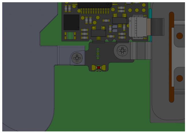
2 external wires, sure, but still 7 solder points on the other flex to bridge, and at least two resistors on the top of the SoC too, just above those two wires.

You're probably right, but there's one thing about those pads still nagging me. Aren't they too big just for soldering wires to? Comparing to the other contact points, I mean. And wouldn't it be weird for TX to go through the trouble of designing those QSBs (yeah, they're actually flex cables, but the purpose looks the same) and then have us soldering wires, and what's worse, soldering them to the flex cable instead of to the main board?

EDIT: main board of the modchip, I mean.
 
Last edited by MrSandstorm,

bakageta

Well-Known Member
Newcomer
Joined
Feb 5, 2016
Messages
77
Trophies
0
XP
169
Country
United States
You're probably right, but there's one thing about those pads still nagging me. Aren't they too big just for soldering wires to? Comparing to the other contact points, I mean. And wouldn't it be weird for TX to go through the trouble of designing those QSBs (yeah, they're actually flex cables, but the purpose looks the same) and then have us soldering wires, and what's worse, soldering them to the flex cable instead of to the main board?

EDIT: main board of the modchip, I mean.

Yeah, those are both valid points on SP1/SP2, I don't know for certain they're for external wires, just speculating there. I originally thought they might be for grounding to the heatpipe for a shorter ground path / less emi / etc, since hardware exploits like this can be picky, but with another pad on the flex cable contacting the shield, I think that's less likely. My main point was a few people in the thread have been saying only 2 points with a video breakdown that said the same, and it's clear that there's 7 on the flex cable near clk, plus 2-4 bridges needed on top of the SoC, aside from the two large SP1/SP2 pads. No one should get their hopes up on this being an easy install, I expect to see plenty of people knocking small components loose or making extra bridges when they try.
 
  • Like
Reactions: Deleted User

MrSandstorm

Well-Known Member
Member
Joined
May 17, 2020
Messages
118
Trophies
0
XP
948
Country
Brazil
Yeah, those are both valid points on SP1/SP2, I don't know for certain they're for external wires, just speculating there. I originally thought they might be for grounding to the heatpipe for a shorter ground path / less emi / etc, since hardware exploits like this can be picky, but with another pad on the flex cable contacting the shield, I think that's less likely. My main point was a few people in the thread have been saying only 2 points with a video breakdown that said the same, and it's clear that there's 7 on the flex cable near clk, plus 2-4 bridges needed on top of the SoC, aside from the two large SP1/SP2 pads. No one should get their hopes up on this being an easy install, I expect to see plenty of people knocking small components loose or making extra bridges when they try.

Yeah, I think most people were hoping for something that they could just stick to the board somewhere and have it working. That might have been caused by some information that came out some time ago* saying "the install looks ultra simple and almost plug and play".
*SOURCE: I can't link it here since my account is too new to post links, but it's another thread here on GBAtemp

Also, I think the SP1 and SP2 markings could be referring to the smaller pads above them, which would make sense considering those will probably have to be soldered to capacitors. (By the way, does anyone here know what package size those caps are? They look like 0402s but I can't really tell)
 

logandzwon

Well-Known Member
Member
Joined
May 2, 2007
Messages
114
Trophies
1
XP
316
Country
United States
There have photos leaked of the lite version installed. There are no random wires attached to the visible solder pads on the mood chip PCB. I think it’s safe to believe in the core it’s two points, and the lite is 2 + whatever the flex cable needs.
 

Kuron3ko

Member
Newcomer
Joined
Oct 10, 2016
Messages
12
Trophies
0
Age
32
XP
55
Country
Malaysia
I'm not a fan of their previous work with the switch. This however looks great, it's good to see them back to doing what they know best. Personally I've thought their hardware offerings were good.
do u mean u not a fan bcos they charge for the sx os that they previously did?

--------------------- MERGED ---------------------------

Yeah, I think most people were hoping for something that they could just stick to the board somewhere and have it working. That might have been caused by some information that came out some time ago* saying "the install looks ultra simple and almost plug and play".
*SOURCE: I can't link it here since my account is too new to post links, but it's another thread here on GBAtemp

Also, I think the SP1 and SP2 markings could be referring to the smaller pads above them, which would make sense considering those will probably have to be soldered to capacitors. (By the way, does anyone here know what package size those caps are? They look like 0402s but I can't really tell)
not sure how to stick, any new technology to stick them on the ns original soldered chip?
 
Last edited by Kuron3ko,

MrSandstorm

Well-Known Member
Member
Joined
May 17, 2020
Messages
118
Trophies
0
XP
948
Country
Brazil
not sure how to stick, any new technology to stick them on the ns original soldered chip?

"Stick" used metaphorically, meaning people hoping for something they could simply plug into something without having to deal with soldering. I meant to say such expectations were unrealistic. I apologise if my wording led to confusion.
 
Last edited by MrSandstorm,

weatMod

Well-Known Member
Member
Joined
Aug 24, 2013
Messages
3,305
Trophies
2
Age
47
XP
3,351
Country
United States
maybe there is no soldering at all maybe TX is just trolling us , or trolling Nintendo and would be cloners to throw them off
maybe that's why they haven't released the details yet :rofl2:
 

The14thfly

Well-Known Member
Member
Joined
May 14, 2018
Messages
178
Trophies
0
XP
2,197
Country
Switzerland
How it works? How to install? Tester why not share video proof? Strange...
tEsTeR wHy NoT sHaRe ViDeO pRoOf?


STRAAANGE


that's because there aren't instructions on how to solder it yet + even if you do manage to do that, you won't be able to use it since sxos 3.0.0 hasn't been released, you genius.
 
  • Like
Reactions: naxil

wurstpistole

GBAtemp MVP
Member
Joined
Nov 19, 2015
Messages
4,654
Trophies
1
XP
5,415
Country
United Kingdom
tEsTeR wHy NoT sHaRe ViDeO pRoOf?


STRAAANGE


that's because there aren't instructions on how to solder it yet + even if you do manage to do that, you won't be able to use it since sxos 3.0.0 hasn't been released, you genius.
I was literally wondering the same - why show the boards yet no mention about how or if they work
but then
why even send the units out when there are no instructions for installation and no software to use them with
how would they test them
 

Litvinkov

Active Member
Newcomer
Joined
Apr 13, 2020
Messages
27
Trophies
0
Age
33
XP
651
Country
Ukraine
I seem to have missed something - what's this about "even if you install it by yourself without instructions it won't work because sx os 3.0.0 is not out yet"? why does the chip need this specific version of sx os? and how would the software on the chip be updated in the future?
 

micp

Well-Known Member
Member
Joined
Apr 3, 2020
Messages
149
Trophies
0
XP
446
Country
United Kingdom
I seem to have missed something - what's this about "even if you install it by yourself without instructions it won't work because sx os 3.0.0 is not out yet"? why does the chip need this specific version of sx os? and how would the software on the chip be updated in the future?

3.0 will come with code specific to the chip that causes the exploit. The modchip also comes with a micro SD input so that could be used to update it.
 

izy

Advanced Tech Pleb
Member
Joined
Sep 17, 2010
Messages
2,311
Trophies
2
XP
4,025
Country
United Kingdom
3.0 will come with code specific to the chip that causes the exploit. The modchip also comes with a micro SD input so that could be used to update it.
If you read the thread the micro USB is mainly for recovery .
It's not specifically for updating the chip in future
 
  • Like
Reactions: peteruk

FR0ZN

Well-Known Member
Member
Joined
Nov 2, 2013
Messages
1,378
Trophies
1
Age
37
XP
3,867
Country
United States
in-switch-exclusivite-ls-les-plans-du-sx-lite-1.png

in-switch-exclusivite-ls-les-plans-du-sx-lite-2.png

in-switch-exclusivite-ls-les-plans-du-sx-lite-3.png

in-switch-exclusivite-ls-les-plans-du-sx-lite-4.png

in-switch-exclusivite-ls-les-plans-du-sx-lite-5.png

in-switch-exclusivite-ls-les-plans-du-sx-lite-6.png

in-switch-exclusivite-ls-les-plans-du-sx-lite-7.png
 

Site & Scene News

Popular threads in this forum

General chit-chat
Help Users
    K3Nv2 @ K3Nv2: Like for micro