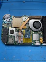
The smallest I have is 30awg.Highly suspect for cold join issue there. Can you try to use normal/wrapping no enameled wires?
You are using an out of date browser. It may not display this or other websites correctly.
You should upgrade or use an alternative browser.
You should upgrade or use an alternative browser.
Staff Posts
Recent threadmarks
sharing files
Important Posts
Recent threadmarks
FirmwaresYup, thats good enough. Just try changing from the easiest ground, 3.3, rst, clk, cmd, d0.The smallest I have is 30awg.
But be carefull as thicker wire can rip apart pcb solder pad.
Last edited by cgtchy0412,
It made no difference. I got it to boot once to the correct screen and when I put the shield on again it’s just a blue lightYup, thats good enough. Just try changing from the easiest ground, 3.3, rst, clk, cmd, d0.
But be carefull as thicker wire can rip apart pcb solder pad.
Attachments
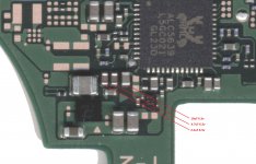
Hey guys, I screwed up (OLED Kiosk model). Everything was going fine until I was bridging the connection for the 3.3v point. I accidentally got solder between some nearby resistors, and ultimately decided to use my hot air gun to pull them off the board.
While this was a good backup solution, I somehow misplaced the resistors, and now I do not know where they are: Does anyone happen to know what the red resistor measurements are? I am considering ordering replacement parts to complete the installation.
I also swear that there was a resistor in the annotated green region: if it exists, can someone confirm it + provide the specs so I can replace that, too?
Last edited by CrispyYoshi,
This happens when you screw up(literal screw) the shield or even when unscrew?It made no difference. I got it to boot once to the correct screen and when I put the shield on again it’s just a blue light
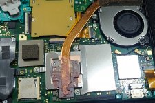
Also please try to cover whole motherboard including pico (yes full cover) with thin plastic before you put the shield.. and see what happens.
And last thing, try to move ground point to here or here
Last edited by cgtchy0412,
It’ll do it both ways. When I say shield I’m referring to the shield over the CPU and than the heat sink. I got it to boot again and am currently modding it. The heat sink is not screwed down.
Also, out of curiosity why should I move the ground point there?
Post automatically merged:
Would it be terrible not to screw down the heat sink?This happens when you screw up(literal screw) the shield or even when unscrew?
Also please try to cover whole motherboard including pico (yes full cover) with thin plastic before you put the shield.. and see what happens.
And last thing, try to move ground point to here or here
View attachment 376847
Also, out of curiosity why should I move the ground point there?

Last edited by BlueBeans,
If it didn't work with 0.1 then u had solderjoint problems , the only wire that needs to be thicker are the 0.2wiresenameled need practice to solder
i need a month to understand how it work.
first im using 0.1mm but doesnt work for my switch
and then 0.2mm
is success for me
Yes it would, you can still get away without the whole soc&ram shield/cover.. but you definitely need to screw down those 3 heatsink leg.Would it be terrible not to screw down the heat sink?
But who knows maybe you can and it wont overheat, cause on Lite never it will enter Dock mode so it wont overheat.. just maybe.
For interference reason... as i once done CPU wire close to Ground wire give issues always boot to ofw, then after i make it far apart it boots normally.Also, out of curiosity why should I move the ground point there?
Well there must be something shorting otherwise u wouldn't have issues while screwing it don't do u have a solder blob on the bottom side of the pico , so when u tighten it don't is pusches on the bottum shield? Are there any lines that are squeezed with the shield?Nothing is shorted to ground, to each other, or anything else.
Post automatically merged:
If its only when ur screwing ur heat shield down I would check the mostfets, to much solder on them or the caps?It’ll do it both ways. When I say shield I’m referring to the shield over the CPU and than the heat sink. I got it to boot again and am currently modding it. The heat sink is not screwed down.
Post automatically merged:
Would it be terrible not to screw down the heat sink?
Also, out of curiosity why should I move the ground point there?
Since there is only a issue when u tighten the heatsink it has to be in that areaa
I always use the exosphere on my all switch. Because it removes the original seriel information, in settings its just a zeros. So, you can ignore a 90dns. While switch tl OFW not sysnand, you will not get banned. You can also use a Hats pack from sthetix github for easy process, because it comes withe exopshere.If i use emummc. That way to inter ofw with out get banned????
you are missing capacitors. I'll see if I can get the values in the meantimeHey guys, I screwed up (OLED Kiosk model). Everything was going fine until I was bridging the connection for the 3.3v point. I accidentally got solder between some nearby resistors, and ultimately decided to use my hot air gun to pull them off the board.
While this was a good backup solution, I somehow misplaced the resistors, and now I do not know where they are: Does anyone happen to know what the red resistor measurements are? I am considering ordering replacement parts to complete the installation.
I also swear that there was a resistor in the annotated green region: if it exists, can someone confirm it + provide the specs so I can replace that, too?View attachment 376862
Edit: @CrispyYoshi
I updated the values (still missing one)
Attachments
Last edited by QuiTim,
Happened to me and it worked when I cut the shield, just use a pen and mark where the pico lies and cut it with a pair of scissors. I'm 90% sure this will fix your problem. I use enameled wires and this has worked for me.I’m going to rip my hair out and throw this switch against the wallevery time I put the heat shield and cover back on it won’t boot. When those are attached and everything is screwed down I get a constant pulsing blue light. I’ve redone everything a half dozen time. Nothing is shorted. Everything is covered. Idk what to do anymore.
So.. second install - This time on a V2 (first was a lite) and this time it went flawlessly.
I probably learnt a few lessons on the way from my failed lite install..
eg: I got some solder mask and used it to ensure no shorted pads.
Also - not sure if it's just me or having gained some experience - but I found that the V2 install was much easier than the lite.
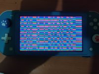
On the lite - I've spent a lot of time digging in to what may be going on and still haven't found a solution - it's strange that I could only get emmc to work when the pico was disconnected from power - but that does cause stability issues with the reset line. I have managed to make a full backup though and will eventually take a look at the dumped data - when I manage to get my keys (if). It does seem though that the problem I'm having on the lite is a DRAM problem - I can use / write payloads that run in IRAM only, but any attempt at using DRAM (stack/heap) causes crashes. On one occasion I kinda managed to get Hekate to "load" but it ended up only displaying a "pixelated" screen with random colors - pretty sure that's a DRAM problem too.
It could be a power issue with the DRAM - but I have no idea where to probe for the DRAM power lines - if anyone knows - I'd be grateful.
Screen like this?So.. second install - This time on a V2 (first was a lite) and this time it went flawlessly.
I probably learnt a few lessons on the way from my failed lite install..
eg: I got some solder mask and used it to ensure no shorted pads.
Also - not sure if it's just me or having gained some experience - but I found that the V2 install was much easier than the lite.
On the lite - I've spent a lot of time digging in to what may be going on and still haven't found a solution - it's strange that I could only get emmc to work when the pico was disconnected from power - but that does cause stability issues with the reset line. I have managed to make a full backup though and will eventually take a look at the dumped data - when I manage to get my keys (if). It does seem though that the problem I'm having on the lite is a DRAM problem - I can use / write payloads that run in IRAM only, but any attempt at using DRAM (stack/heap) causes crashes. On one occasion I kinda managed to get Hekate to "load" but it ended up only displaying a "pixelated" screen with random colors - pretty sure that's a DRAM problem too.
It could be a power issue with the DRAM - but I have no idea where to probe for the DRAM power lines - if anyone knows - I'd be grateful.

Attachments
My friend has a V1 unpatched, he tried to update the atmosphere and now there is no sign of life on switch. Not even a battery charging sign.
Tried Hard reset nothing worked.
Any idea?
I also don't had this switch with me right now.
Edit: Does Picofly work on Unpatched switch?because I don't have a trinketMo
Tried Hard reset nothing worked.
Any idea?
I also don't had this switch with me right now.
Edit: Does Picofly work on Unpatched switch?because I don't have a trinketMo
Last edited by bilalhassan341,
Have you tried the experiment firmware from rehius?So.. second install - This time on a V2 (first was a lite) and this time it went flawlessly.
I probably learnt a few lessons on the way from my failed lite install..
eg: I got some solder mask and used it to ensure no shorted pads.
Also - not sure if it's just me or having gained some experience - but I found that the V2 install was much easier than the lite.
On the lite - I've spent a lot of time digging in to what may be going on and still haven't found a solution - it's strange that I could only get emmc to work when the pico was disconnected from power - but that does cause stability issues with the reset line. I have managed to make a full backup though and will eventually take a look at the dumped data - when I manage to get my keys (if). It does seem though that the problem I'm having on the lite is a DRAM problem - I can use / write payloads that run in IRAM only, but any attempt at using DRAM (stack/heap) causes crashes. On one occasion I kinda managed to get Hekate to "load" but it ended up only displaying a "pixelated" screen with random colors - pretty sure that's a DRAM problem too.
It could be a power issue with the DRAM - but I have no idea where to probe for the DRAM power lines - if anyone knows - I'd be grateful.

I have Kapton tape covering the shield where the pico sits. It has to be something to do with the cable but I have no idea. i changed it 3 times so I have no idea what it could be. At this point, I almost prefer the mosfets.Well there must be something shorting otherwise u wouldn't have issues while screwing it don't do u have a solder blob on the bottom side of the pico , so when u tighten it don't is pusches on the bottum shield? Are there any lines that are squeezed with the shield?
Post automatically merged:
If its only when ur screwing ur heat shield down I would check the mostfets, to much solder on them or the caps?
Since there is only a issue when u tighten the heatsink it has to be in that areaa
Hi,
I am getting screen flickering, slow performance and black lines when I boot to the CFW or OFW on a switch oled. Overall its glitchy and slow, but works fine in Hekate.
I installed the picofly and when I was installing it I noticed that, with the multimeter in Diode Mode, I was getting ~0.355v from the CPU. I am using a V2 ribbon cable from the Hwfly modchip. Could this be the issue?
Unfortunately, mine is when I screw down the heat sink, not the metal back cover. I haven't even gotten to that one yet.Happened to me and it worked when I cut the shield, just use a pen and mark where the pico lies and cut it with a pair of scissors. I'm 90% sure this will fix your problem. I use enameled wires and this has worked for me.
Similar threads
- Replies
- 3
- Views
- 1K
- Replies
- 2
- Views
- 342
- Replies
- 42
- Views
- 6K
Site & Scene News
New Hot Discussed
-
-
23K views
Wii U and 3DS online services shutting down today, but Pretendo is here to save the day
Today, April 8th, 2024, at 4PM PT, marks the day in which Nintendo permanently ends support for both the 3DS and the Wii U online services, which include co-op play...by ShadowOne333 179 -
18K views
Nintendo Switch firmware update 18.0.1 has been released
A new Nintendo Switch firmware update is here. System software version 18.0.1 has been released. This update offers the typical stability features as all other... -
16K views
The first retro emulator hits Apple's App Store, but you should probably avoid it
With Apple having recently updated their guidelines for the App Store, iOS users have been left to speculate on specific wording and whether retro emulators as we... -
16K views
Delta emulator now available on the App Store for iOS
The time has finally come, and after many, many years (if not decades) of Apple users having to side load emulator apps into their iOS devices through unofficial...by ShadowOne333 96 -
15K views
MisterFPGA has been updated to include an official release for its Nintendo 64 core
The highly popular and accurate FPGA hardware, MisterFGPA, has received today a brand new update with a long-awaited feature, or rather, a new core for hardcore...by ShadowOne333 54 -
11K views
Nintendo takes down Gmod content from Steam's Workshop
Nintendo might just as well be a law firm more than a videogame company at this point in time, since they have yet again issued their now almost trademarked usual...by ShadowOne333 113 -
11K views
TheFloW releases new PPPwn kernel exploit for PS4, works on firmware 11.00
TheFlow has done it again--a new kernel exploit has been released for PlayStation 4 consoles. This latest exploit is called PPPwn, and works on PlayStation 4 systems... -
10K views
A prototype of the original "The Legend of Zelda" for NES has been found and preserved
Another video game prototype has been found and preserved, and this time, it's none other than the game that spawned an entire franchise beloved by many, the very...by ShadowOne333 31 -
9K views
Anbernic reveals specs details of pocket-sized RG28XX retro handheld
Anbernic is back with yet another retro handheld device. The upcoming RG28XX is another console sporting the quad-core H700 chip of the company's recent RG35XX 2024... -
9K views
Nintendo "Indie World" stream announced for April 17th, 2024
Nintendo has recently announced through their social media accounts that a new Indie World stream will be airing tomorrow, scheduled for April 17th, 2024 at 7 a.m. PT...by ShadowOne333 53
-
-
-
179 replies
Wii U and 3DS online services shutting down today, but Pretendo is here to save the day
Today, April 8th, 2024, at 4PM PT, marks the day in which Nintendo permanently ends support for both the 3DS and the Wii U online services, which include co-op play...by ShadowOne333 -
113 replies
Nintendo takes down Gmod content from Steam's Workshop
Nintendo might just as well be a law firm more than a videogame company at this point in time, since they have yet again issued their now almost trademarked usual...by ShadowOne333 -
97 replies
The first retro emulator hits Apple's App Store, but you should probably avoid it
With Apple having recently updated their guidelines for the App Store, iOS users have been left to speculate on specific wording and whether retro emulators as we...by Scarlet -
96 replies
Delta emulator now available on the App Store for iOS
The time has finally come, and after many, many years (if not decades) of Apple users having to side load emulator apps into their iOS devices through unofficial...by ShadowOne333 -
79 replies
Nintendo Switch firmware update 18.0.1 has been released
A new Nintendo Switch firmware update is here. System software version 18.0.1 has been released. This update offers the typical stability features as all other...by Chary -
76 replies
TheFloW releases new PPPwn kernel exploit for PS4, works on firmware 11.00
TheFlow has done it again--a new kernel exploit has been released for PlayStation 4 consoles. This latest exploit is called PPPwn, and works on PlayStation 4 systems...by Chary -
55 replies
Nintendo Switch Online adds two more Nintendo 64 titles to its classic library
Two classic titles join the Nintendo Switch Online Expansion Pack game lineup. Available starting April 24th will be the motorcycle racing game Extreme G and another...by Chary -
54 replies
MisterFPGA has been updated to include an official release for its Nintendo 64 core
The highly popular and accurate FPGA hardware, MisterFGPA, has received today a brand new update with a long-awaited feature, or rather, a new core for hardcore...by ShadowOne333 -
53 replies
Nintendo "Indie World" stream announced for April 17th, 2024
Nintendo has recently announced through their social media accounts that a new Indie World stream will be airing tomorrow, scheduled for April 17th, 2024 at 7 a.m. PT...by ShadowOne333 -
52 replies
The FCC has voted to restore net neutrality, reversing ruling from 2017
In 2017, the United States Federal Communications Commission (FCC) repealed net neutrality. At the time, it was a major controversy between internet service providers...by Chary
-
Popular threads in this forum
General chit-chat
-
 The Real Jdbye
Loading…*is birb*
 -
 Psionic Roshambo
Loading…
 -
 K3Nv2
Loading…
 -
 realtimesave
Loading…
-
-
-
-
-
-
-
-
-
-
-
-
-
-
 @
Psionic Roshambo:
I'm curious.... Is PCSX2 compatible with normal web cams emulating the EyeToy....
 -
-
-
 @
Psionic Roshambo:
Just looked it up and yes you can use web cams on PCSX2 to play EyeToy games lol
 -
-
-
-
-
-
-
-


 .
.
