You are using an out of date browser. It may not display this or other websites correctly.
You should upgrade or use an alternative browser.
You should upgrade or use an alternative browser.
Staff Posts
Recent threadmarks
sharing files
Important Posts
Recent threadmarks
FirmwaresView attachment 369293
If you fancy filling in the missing for Switch Lite, please do or send a message, so people have proper diagrams
(Note: I filled in the missing info using the guide)
ThanksView attachment 369295
(Note: I filled in the missing info using the guide)
- Joined
- Jan 11, 2015
- Messages
- 754
- Trophies
- 0
- Age
- 36
- Location
- Makati
- Website
- leerz25.sitesled.com
- XP
- 2,213
- Country

show your cpu cap soldering, you might have killed the cap and shorted it. remove the overheating cap and focus on the other cap.It's start, tnx. But few minutes overheated and fell off mosfet with smoke. How fix it? Need new mosfet?
- Joined
- Oct 29, 2013
- Messages
- 1,457
- Trophies
- 1
- Location
- Brazil, Sao Paulo
- Website
- www.gamemod.com.br
- XP
- 1,673
- Country

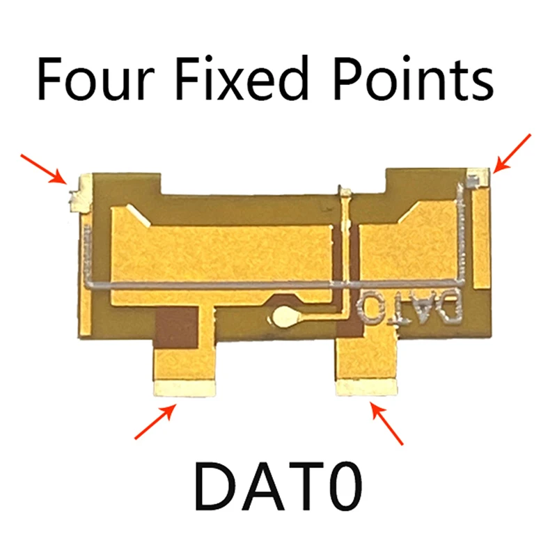
Does anyone know whether there any open source project for this D0 adapter?


I was making, but failedDoes anyone know whether there any open source project for this D0 adapter?

https://www.pcbway.com/project/shareproject/D0_adapter_for_BGA153.htmlDoes anyone know whether there any open source project for this D0 adapter?

Might need modified
I dunno but the fact it has 3 resistors on it is susHas anyone tried using an rp2040 tiny instead of a zero?
images are pretty self explanatory, if you cant understand them then you should have someone else do it for youHey nothing against your guide it's very well, but I think most others including me would rather a complete picture, showing the full board and the wires
They are not really complete images - would be better the way mine are so people can see the exact location and where to go from and to
Example - This is half an image
View attachment 369288
This doesn't really explain
View attachment 369290
I haven't measured it exactly. I took some enameled wire off of a coil from a relayNice. What AWG/MM Did you use?
Post automatically merged:
I also had to cut metal shielding of my Switch V2, then it closed all right. When soldering a mosfet to the caps i haven't used a microscope - I don't have one, everything was done by sight (I have at least 10 years with soldering experience) but still, it was difficult
Last edited by Verity,
Looks like around 0.4 or 0.5ish.I haven't measured it exactly. I took some enameled wire off of a coil from a relay
Post automatically merged:
View attachment 369345View attachment 369346
I also had to cut metal shielding of my Switch V2, then it closed all right. When soldering a mosfet to the caps i haven't used a microscope - I don't have one, everything was done by sight (I have at least 10 years with soldering experience) but still, it was difficult
 I use wire from a phone speaker for low current connects. Looks to be about 0.1mm.
Do we have any surprises with the new OLED Zelda Ed.?
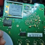
Saw a pic few days ago here that it got a TOSHIBA NAND, does the FW2.67 works flawlessly without additional tweaks (I mean, with only 3x47 Ohm resistors on data line)?
Saw a pic few days ago here that it got a TOSHIBA NAND, does the FW2.67 works flawlessly without additional tweaks (I mean, with only 3x47 Ohm resistors on data line)?
Last edited by Phantomas77,
See pico fly aio...Hi are all oled EMMC is supported I get Pink light on 3 console ¿ Cant solved it
Led erorLED must be RED after USB write. if you see green, set "RGB mode" jumper
WHITE = eMMC write
BLUE = glitch
PURPLE = eMMC boot failure, check CMD / CLK
YELLOW = eMMC write failure, check D0 / unsupported eMMC
CYAN = no reaction to glitch, check mosfet wire
GREEN = success
Similar threads
- Replies
- 5
- Views
- 2K
- Replies
- 2
- Views
- 810
- Replies
- 42
- Views
- 7K
Site & Scene News
New Hot Discussed
-
-
38K views
New static recompiler tool N64Recomp aims to seamlessly modernize N64 games
As each year passes, retro games become harder and harder to play, as the physical media begins to fall apart and becomes more difficult and expensive to obtain. The... -
16K views
Majora’s Mask PC port 2Ship2Harkinian gets its first release
After several months of work, the Harbour Masters 64 team have released their first public build of 2Ship2Harkinian, a feature-rich Majora's Mask PC port. This comes... -
16K views
Anbernic reveals the RG35XXSP, a GBA SP-inspired retro handheld
Retro handheld manufacturer Anbernic has revealed its first clamshell device: the Anbernic RG35XXSP. As the suffix indicates, this handheld's design is inspired by... -
16K views
Mario Builder 64 is the N64's answer to Super Mario Maker
With the vast success of Super Mario Maker and its Switch sequel Super Mario Maker 2, Nintendo fans have long been calling for "Maker" titles for other iconic genres... -
15K views
"Nintendo World Championships: NES Edition", a new NES Remix-like game, launching July 18th
After rumour got out about an upcoming NES Edition release for the famed Nintendo World Championships, Nintendo has officially unveiled the new game, titled "Nintendo...by ShadowOne333 79 -
12K views
Ubisoft reveals 'Assassin's Creed Shadows' which is set to launch later this year
Ubisoft has today officially revealed the next installment in the Assassin's Creed franchise: Assassin's Creed Shadows. This entry is set in late Sengoku-era Japan... -
12K views
RetroArch is now available in the Apple Store for iOS devices
Another day, another great emulator that makes its way into the Apple Store for more users to enjoy. With Apple opening its store up to videogame emulators earlier...by ShadowOne333 58 -
11K views
The Kingdom Hearts games are coming to Steam
After a little more than three years of exclusivity with the Epic Games Store, Square Enix has decided to bring their beloved Kingdom Hearts franchise to Steam. The... -
10K views
The founder of Oculus is releasing a $199 FPGA Game Boy system
Palmer Luckey is known for his pursuits into the world of virtual reality, having founded Oculus and designed the Rift VR headset. Prior to the $2 billion dollar... -
10K views
Asus reveals the ROG Ally X, with better battery life and more "repair-friendly" design
Drumming up hype by teasing a new product, with its formal reveal to come next month is Asus, who just announced the latest revision to their ROG Ally handheld...
-
-
-
161 replies
The founder of Oculus is releasing a $199 FPGA Game Boy system
Palmer Luckey is known for his pursuits into the world of virtual reality, having founded Oculus and designed the Rift VR headset. Prior to the $2 billion dollar...by Chary -
144 replies
New static recompiler tool N64Recomp aims to seamlessly modernize N64 games
As each year passes, retro games become harder and harder to play, as the physical media begins to fall apart and becomes more difficult and expensive to obtain. The...by Chary -
103 replies
Majora’s Mask PC port 2Ship2Harkinian gets its first release
After several months of work, the Harbour Masters 64 team have released their first public build of 2Ship2Harkinian, a feature-rich Majora's Mask PC port. This comes...by Scarlet -
96 replies
Ubisoft reveals 'Assassin's Creed Shadows' which is set to launch later this year
Ubisoft has today officially revealed the next installment in the Assassin's Creed franchise: Assassin's Creed Shadows. This entry is set in late Sengoku-era Japan...by Prans -
88 replies
The Kingdom Hearts games are coming to Steam
After a little more than three years of exclusivity with the Epic Games Store, Square Enix has decided to bring their beloved Kingdom Hearts franchise to Steam. The...by Chary -
79 replies
"Nintendo World Championships: NES Edition", a new NES Remix-like game, launching July 18th
After rumour got out about an upcoming NES Edition release for the famed Nintendo World Championships, Nintendo has officially unveiled the new game, titled "Nintendo...by ShadowOne333 -
72 replies
Nintendo takes down the Breath of the Wild randomizer mod from Gamebanana
Another day, another Nintendo DMCA takedown against fan-made content. Just a few minutes ago, Nintendo issued a DMCA takedown notice against a widely known and...by ShadowOne333 -
67 replies
Select PlayStation 2 games are coming to PlayStation 5
Sony is once more attempting to reintroduce players to their older library of games by re-releasing classic PlayStation 2 titles onto the PlayStation Store. During...by Chary -
65 replies
Anbernic reveals the RG35XXSP, a GBA SP-inspired retro handheld
Retro handheld manufacturer Anbernic has revealed its first clamshell device: the Anbernic RG35XXSP. As the suffix indicates, this handheld's design is inspired by...by Prans -
64 replies
Mario Builder 64 is the N64's answer to Super Mario Maker
With the vast success of Super Mario Maker and its Switch sequel Super Mario Maker 2, Nintendo fans have long been calling for "Maker" titles for other iconic genres...by Scarlet
-
Popular threads in this forum
General chit-chat
-
 K3Nv2
Loading…
 -
 BakerMan
Loading…I rather enjoy a life of taking it easy. I haven't reached that life yet though.
-
-
-
-
-
-
-
-
-
-
-
-
-
-
 @
BakerMan:
yo guys the sonic x shadow generations trailer dropped today, and shadow just straight up decided, and i hate (love) to bring this dead meme up, but, it's morbin time
 -
 @
BakerMan:
also the game drops oct 25, so does call of duty black ops 6, i guess barbenheimer is happening again
 -
-
-
-
-
-
-
-
-
-


