Hacking Hardware Picofly - a HWFLY switch modchip

cicci084

Well-Known Member
Member
Joined
Apr 1, 2023
Messages
146
Trophies
0
Age
44
XP
239
Country
Italy
Hi guys.

I already wrote in the past, then I forgot.

A switch that starts only in cfw emummc and does not wake up from standby.

I unsoldered picofly (only left mosfet on CPU, not connected to chip).

Even without chi it won't start, just black screen

Can the mosfet alone be annoying?

I remember the mod had the mosfet pin > to CPU shorted to ground.

I can get the keys, with these keys, can I rebuild a new nand taken from another switch?

On the picofly I put double 47 resistors.
 

Beaver_27

Member
Newcomer
Joined
May 19, 2023
Messages
8
Trophies
0
Age
21
XP
37
Country
Romania
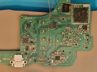
Hi, i have bridged the two 3.3v caps on the switch v2 motherboard, is it fine to leave it like this? I've been struggling to get the excess solder off.
 

Attachments

  • Snapshot000001.jpg
    Snapshot000001.jpg
    76.1 KB · Views: 30

GBAn00b1e

Member
Newcomer
Joined
Aug 12, 2023
Messages
6
Trophies
0
XP
127
Country
United States
Hi, i have bridged the two 3.3v caps on the switch v2 motherboard, is it fine to leave it like this? I've been struggling to get the excess solder off.
what are you using to take the excess solder off?
Post automatically merged:

Hi, i have bridged the two 3.3v caps on the switch v2 motherboard, is it fine to leave it like this? I've been struggling to get the excess solder off.
Also, where on the board is that?
 

Beaver_27

Member
Newcomer
Joined
May 19, 2023
Messages
8
Trophies
0
Age
21
XP
37
Country
Romania
what are you using to take the excess solder off?
I tryed a wick and it didn't work, I don't have a desoldering pen but i bought one and it will arrive in a week so maybe that would help, and just the heat up and try to move the solder with the iron/tweezers.
Also this where it is on the board.
 

Attachments

  • 20230812_150143.jpg
    20230812_150143.jpg
    3.5 MB · Views: 36

GBAn00b1e

Member
Newcomer
Joined
Aug 12, 2023
Messages
6
Trophies
0
XP
127
Country
United States
I tryed a wick and it didn't work, I don't have a desoldering pen but i bought one and it will arrive in a week so maybe that would help, and just the heat up and try to move the solder with the iron/tweezers.
Also this where it is on the board.
Ok I think that is right nex to the M9 chip. I personally wouldn't leave it like that, but i can check to see if one of those sides is ground and the other isn't. I would use a rework station with a pair of tweezers, but you just have to be careful with the temp and airflow since too much heat is bad and too much airflow will send things to the second dimesnion. You might also be able to use hot tweezers. I had a similar situation before and I used FLUX with braided wick to remove excess solder. I then heated up with soldering iron and separated with a tweezer.
 

cgtchy0412

Well-Known Member
Member
Joined
Apr 26, 2023
Messages
287
Trophies
0
Age
41
XP
436
Country
Indonesia
I tryed a wick and it didn't work, I don't have a desoldering pen but i bought one and it will arrive in a week so maybe that would help, and just the heat up and try to move the solder with the iron/tweezers.
Also this where it is on the board.
That solder suction will do... just heat ONLY the bridged point with lots of flux then suck it.
Dont heat entire caps body or you will suck those caps from motherboard.
Next time on V2 just use 3.3 v from emmc module.
 
  • Like
Reactions: QuiTim

abal1000x

Well-Known Member
Member
Joined
Jun 5, 2022
Messages
1,070
Trophies
0
XP
1,395
Country
Gaza Strip
I tryed a wick and it didn't work, I don't have a desoldering pen but i bought one and it will arrive in a week so maybe that would help, and just the heat up and try to move the solder with the iron/tweezers.
Also this where it is on the board.
You need to use lot of flux on it, so the heat are distributed, then use the wick
 
  • Like
Reactions: QuiTim

superxoi

Well-Known Member
Member
Joined
May 8, 2020
Messages
164
Trophies
0
Age
32
XP
856
Country
Vietnam
Hi, i have bridged the two 3.3v caps on the switch v2 motherboard, is it fine to leave it like this? I've been struggling to get the excess solder off.
i took both off then placed it back again.
Post automatically merged:

hello friend. i intend to do more picofly mod. This time i will add 2x 47ohm. 1 question i want to ask you guys is that i saw a lot of pics people did the backmosfet with a resistor on the mosfet. May i ask you guy what is the value of it? because so far i haven't add any resistor on the mosfet yet.
 
Last edited by superxoi,

Beaver_27

Member
Newcomer
Joined
May 19, 2023
Messages
8
Trophies
0
Age
21
XP
37
Country
Romania
That solder suction will do... just heat ONLY the bridged point with lots of flux then suck it.
Dont heat entire caps body or you will suck those caps from motherboard.
Next time on V2 just use 3.3 v from emmc module.
Heat them with a heating gun or soldering iron? I have both but i never used a solder suction. Also if i use the heat gun I'll just kapton tape all the surrounding stuff. Thank you for the suggestions tho
 

mrdude

Developer
Developer
Joined
Dec 11, 2015
Messages
3,071
Trophies
1
Age
56
XP
8,237
You need to use lot of flux on it, so the heat are distributed, then use the wick
I usually dip the wick in flux first and cover the componet in solder, and freshly tip my iron with low melt solder, and put some low melt solder on the part I am removing. In this case, plent flux and a fluxed braid with a chisel tip on the iron to heat the braid up then put the braid onto the solder to be removed.
 
  • Like
Reactions: QuiTim

Switxh

Well-Known Member
Member
Joined
Mar 11, 2023
Messages
110
Trophies
0
Age
28
XP
273
Country
United Kingdom
Heat them with a heating gun or soldering iron? I have both but i never used a solder suction. Also if i use the heat gun I'll just kapton tape all the surrounding stuff. Thank you for the suggestions tho
Honestly for me personally, trying to use wick for a bridge like that is kind of tricky. The best way for me is to just use the hot air station to remove the caps. Just by doing that it usually clears the bridge, then you can just re position the caps. Or if needed, you can remove the excess solder with an iron before you put the caps back on. I find that if I try to use solder braid in areas like that it just sticks to all the other caps and components around the area I'm trying to suck the solder from. I only really use it on bare pads. That's just my personal experience though, for what it's worth.
 

Takezo-San

Well-Known Member
Member
Joined
May 3, 2023
Messages
261
Trophies
0
Age
39
XP
349
Country
Seychelles
So my stencil crapped out on me for the reball. Taped it down on the jig with tweezers for pressure but no matter what, the sudden warp under heat would give uneven sized reballs on the chip. Tried to see if it would still boot but nothing. After 3-4 failed attempts, i gave up and hand reballed all 153 on the emmc. But I ran into a problem where I had cleaned off the solder off the chip so many times, that some of the pads were larger and worn away so consequently when the reball would happen, those particular ball formations would be smaller than the others and hence no connection.
So I had to use solder mask to make the best patches around the circular pads as possible and even on a pad that was bridging on the motherboard. I got proficient at it and half hour later of reballing by hand (first use thin layer of flux on the chip so the balls have something minuscule to adhere too), speed turned all the way down on the heat station couple minutes later....balls turned out all even, shiny and honestly better than stencil jobs. Booted perfectly well and saved an OLED. Hope this helps someone down the line or someone looking for a cost effective way to do this. All you need is the 30mm ball, a small pin and flux and patience. Thats it.

20230808_191601 (1).jpg


Edit - 0.30mm balls not 30mm lol
 
Last edited by Takezo-San,

Moromoromoro

Member
Newcomer
Joined
May 18, 2023
Messages
7
Trophies
0
Age
29
XP
200
Country
United Kingdom
Just a quick one in regards to the OLED D point,

if the via and the trace between is broken but you have soldered the cable to the trace the chip is likely to flash emmc init failure due to the clk point being broken between apu and nand? I am just wondering if there is any alternate point to solder this clk from trace to initialise the nand or i have to grab one of the nand breakboards (hwfly v5) and solder directly to "save" this oled?

EDIT: I have answered the question myself, yes it will give out emmc init fail. jumped the trace extra carefully and now its working ok.
 
Last edited by Moromoromoro,
  • Like
Reactions: floxcap and QuiTim

superxoi

Well-Known Member
Member
Joined
May 8, 2020
Messages
164
Trophies
0
Age
32
XP
856
Country
Vietnam
So my stencil crapped out on me for the reball. Taped it down on the jig with tweezers for pressure but no matter what, the sudden warp under heat would give uneven sized reballs on the chip. Tried to see if it would still boot but nothing. After 3-4 failed attempts, i gave up and hand reballed all 153 on the emmc. But I ran into a problem where I had cleaned off the solder off the chip so many times, that some of the pads were larger and worn away so consequently when the reball would happen, those particular ball formations would be smaller than the others and hence no connection.
So I had to use solder mask to make the best patches around the circular pads as possible and even on a pad that was bridging on the motherboard. I got proficient at it and half hour later of reballing by hand (first use thin layer of flux on the chip so the balls have something minuscule to adhere too), speed turned all the way down on the heat station couple minutes later....balls turned out all even, shiny and honestly better than stencil jobs. Booted perfectly well and saved an OLED. Hope this helps someone down the line or someone looking for a cost effective way to do this. All you need is the 30mm ball, a small pin and flux and patience. Thats it.

View attachment 388004
if your ball was uneven you use a small knife to cut off the excess ball and reheat it, and if the balls are smaller than the other you can apply solder paste and reheat it again then all will be even.
 
  • Like
Reactions: Takezo-San

jkyoho

Well-Known Member
Member
Joined
Sep 2, 2020
Messages
1,305
Trophies
0
Age
39
Location
TORONTO
Website
form.jotform.com
XP
2,244
Country
Canada
So my stencil crapped out on me for the reball. Taped it down on the jig with tweezers for pressure but no matter what, the sudden warp under heat would give uneven sized reballs on the chip. Tried to see if it would still boot but nothing. After 3-4 failed attempts, i gave up and hand reballed all 153 on the emmc. But I ran into a problem where I had cleaned off the solder off the chip so many times, that some of the pads were larger and worn away so consequently when the reball would happen, those particular ball formations would be smaller than the others and hence no connection.
So I had to use solder mask to make the best patches around the circular pads as possible and even on a pad that was bridging on the motherboard. I got proficient at it and half hour later of reballing by hand (first use thin layer of flux on the chip so the balls have something minuscule to adhere too), speed turned all the way down on the heat station couple minutes later....balls turned out all even, shiny and honestly better than stencil jobs. Booted perfectly well and saved an OLED. Hope this helps someone down the line or someone looking for a cost effective way to do this. All you need is the 30mm ball, a small pin and flux and patience. Thats it.

View attachment 388004
30mm ball is gonna be huuuuuuuge:rofl2::rofl2:
 

Attachments

  • PXL_20230812_234157908.jpg
    PXL_20230812_234157908.jpg
    3.1 MB · Views: 35
  • PXL_20230812_234554484.jpg
    PXL_20230812_234554484.jpg
    2.7 MB · Views: 32

cgtchy0412

Well-Known Member
Member
Joined
Apr 26, 2023
Messages
287
Trophies
0
Age
41
XP
436
Country
Indonesia
Heat them with a heating gun or soldering iron? I have both but i never used a solder suction. Also if i use the heat gun I'll just kapton tape all the surrounding stuff. Thank you for the suggestions tho
Iron is enough, need to localize the heat for safe suctioning.
 

Dee87

Well-Known Member
Member
Joined
Mar 19, 2023
Messages
1,139
Trophies
1
XP
1,588
Country
Germany
Just a quick one in regards to the OLED D point,

if the via and the trace between is broken but you have soldered the cable to the trace the chip is likely to flash emmc init failure due to the clk point being broken between apu and nand? I am just wondering if there is any alternate point to solder this clk from trace to initialise the nand or i have to grab one of the nand breakboards (hwfly v5) and solder directly to "save" this oled?

EDIT: I have answered the question myself, yes it will give out emmc init fail. jumped the trace extra carefully and now its working ok.

There is no D point on the picofly install.

So I guess ur installing one of those hwfly or clone and that means u are in the wrong thread. Those are no Picofly so search the hwfly rp2040 thread
 
  • Like
Reactions: Takezo-San

QuiTim

Well-Known Member
Member
Joined
Mar 30, 2023
Messages
756
Trophies
0
XP
1,172
Country
Albania
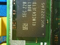
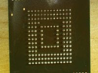
I finally got my hands on the Zelda Oled that I ordered 3 months ago and I decided to try and set a proper dat0 by removing the emmc.

A couple of things to point out:
- It was easier than I thought but I've been preparing/practicing for this for quite some time so for anyone reading this I would suggest you do your homework before diving in.
- The amount of beating these chips can handle is quite impressive.
- Same as Takezo-San wrote a couple of post above, I had no luck with stencil and paste (maybe I was stressed and tired because I started doing this at 11pm) so after trying a couple of times and failed I just did it manually one by one with 0.3 balls.
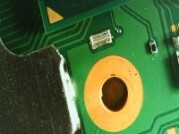
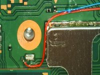
Everything went smoothly afterwards and since the board was already off I also decided to try the abal's mosfet placement on the back of the apu.
I just want to say that this is an amazing thread with some amazing people and the list of people to say thank you is way too long but I have to point out @Dee87 and @Takezo-San without whom I probably would have not had the courage/will to go through with this process and a special thanks to @abal1000x who’s dedication and contribution to this whole mod is priceless.
Below you can see some pictures, I should have done more but I got carried away in the heat of the moment :D
Edit: It goes without saying that without Rehius none of this would even be possible so... :bow: :bow: :bow:
 

Attachments

  • IMG_002.JPG
    IMG_002.JPG
    836 KB · Views: 17
  • IMG_001.JPG
    IMG_001.JPG
    549.5 KB · Views: 19
  • IMG_005.JPG
    IMG_005.JPG
    543 KB · Views: 19
  • IMG_006.JPG
    IMG_006.JPG
    704 KB · Views: 27
  • 20230811_182241.jpg
    20230811_182241.jpg
    1.1 MB · Views: 31
Last edited by QuiTim,

floxcap

Well-Known Member
Newcomer
Joined
May 21, 2023
Messages
69
Trophies
0
XP
281
Country
Australia
I finally got my hands on the Zelda Oled that I ordered 3 months ago and I decided to try and set a proper dat0 by removing the emmc.

A couple of things to point out:
- It was easier than I thought but I've been preparing/practicing this for quite some time so for anyone reading this I would suggest you do your homework before diving in.
- The amount of beating these chips can handle is quite impressive.
- Same as Takezo-San wrote a couple of post above, I had no luck with stencil and paste (maybe I was stressed and tired because I started doing this at 11pm) so after trying a couple of times and failed I just did it manually one by one with 0.3 balls.
Everything went smoothly afterwards and since the board was already off I also decided to try the abal's mosfet placement on the back of the apu.
I just want to say that this is an amazing thread with some amazing people and the list of people to say thank you is way too long but I have to point out @Dee87 and @Takezo-San without whom I probably would have not had the courage/will to go through with this process and a special thanks to @abal1000x who’s dedication and contribution to this whole mod is priceless.
Below you can see some pictures, I should have done more but I got carried away in the heat of the moment :D
Looks awesome @QuiTim !

You've inspired me to practice and give it at go at some point.

In the meantime first I have to see if I can replace a MAX77812 on a lite (first device I tried to mod) as I'm pretty sure that's why I have a BSOD/partial boot/no DRAM on that one. (All the others since have gone perfectly).

Definitely credits to the leaders here :)
 
  • Like
Reactions: Takezo-San

snaker

Well-Known Member
Member
Joined
Mar 30, 2009
Messages
217
Trophies
1
Website
biohazard-era.blogspot.com
XP
691
Country
United States
So my stencil crapped out on me for the reball. Taped it down on the jig with tweezers for pressure but no matter what, the sudden warp under heat would give uneven sized reballs on the chip. Tried to see if it would still boot but nothing. After 3-4 failed attempts, i gave up and hand reballed all 153 on the emmc. But I ran into a problem where I had cleaned off the solder off the chip so many times, that some of the pads were larger and worn away so consequently when the reball would happen, those particular ball formations would be smaller than the others and hence no connection.
So I had to use solder mask to make the best patches around the circular pads as possible and even on a pad that was bridging on the motherboard. I got proficient at it and half hour later of reballing by hand (first use thin layer of flux on the chip so the balls have something minuscule to adhere too), speed turned all the way down on the heat station couple minutes later....balls turned out all even, shiny and honestly better than stencil jobs. Booted perfectly well and saved an OLED. Hope this helps someone down the line or someone looking for a cost effective way to do this. All you need is the 30mm ball, a small pin and flux and patience. Thats it.

View attachment 388004
Congratulations! But it will take you very long time to finish and it is not an efficient way.
I see many people go the reballing way and at least i want to help giving some info for those having a hard time.

Here are some of the most important tips that you must use while reballing a chip using a stencil:

First of all use flux on chip and mix leaded solder on the no lead balls and place the stencil over the chip.

Take some ammount of low melt soldering paste with your spudger and press it 4-5 times on the paper towel to remove as much flux as you can from the soldering paste. This is extremely helpful for newcomers as it will minimize bubbling of the soldering paste during the reballing procedure.

Use the spudger to apply the soldering paste over the stencil multiple times to fill very well the holes and clean the excess soldering paste also very well. Use you tweezers to press down the stencil above and bellow the emmc.Give it a good amount of pressure! This is extremely important especially on low quality stencils. 3d stencils are the best because they are thicker and they do not tend to bend easily! Cheap stencils are not thick and they bend very quickly and this is the main reason that soldering balls under the chip are getting mixed up!

If you use quick 861dw which is one of the most used hot air stations worldwide use 335 and 12 airflow. Temps and airflows vary from station to station so you must find your unique sweet spot. The main idea though is slow airflow moderate temp. You need higher temp than normal because you have very little airlow. Keep pressing down using your tweezers as metioned above! Start from the bottom left very slowly forming the balls to the top right. When done lift your tweezers.

Remove the stencil with the help of some isopropil alcohol if needed, add some flux on the balls and do a reflow.

If you do these steps i guarantee you that you will have success every single time, first try!

Little pressure of the stencil, bubbling of soldering paste and high air flows are the three main reasons of failed reballings.

Reballings can be done with very cheap stencils and very cheap hot air stations and without any of these tips i mentioned above if you have the right experience!!
But if you try these stuff for the first time use these tips and you will be fine!
 
Last edited by snaker,

Site & Scene News

Popular threads in this forum

General chit-chat
Help Users
  • No one is chatting at the moment.
    The Real Jdbye @ The Real Jdbye: @BakerMan needs more expand dong