Hacking Hardware Picofly - a HWFLY switch modchip

Dee87

Well-Known Member
Member
Joined
Mar 19, 2023
Messages
1,139
Trophies
1
XP
1,589
Country
Germany
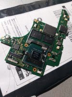
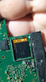
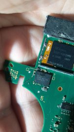
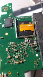
Hi guys, i plan to do an emmc reball, can i use .35 ball instead of .30 ? as i see my emmc chip is becoming a little concave so it should needs higher solder ball?
Any thought?
i wouldnt use bigger balls , the bigger they are u closer they get to touching.

how much heat did u add to it ?
 
  • Like
Reactions: Switxh

NooBziN

Well-Known Member
Member
Joined
Apr 28, 2016
Messages
176
Trophies
0
Age
38
XP
458
Country
Brazil
I have not experienced any issues with this joycon, and it is my own personal switch that I bought off Ebay, so I am not concerned about Ninty's little warranty, I do my own console repairs.
I say this for those who don't want to have problems, that's all
 

aleciobr

Member
Newcomer
Joined
Jun 27, 2023
Messages
22
Trophies
0
Age
32
XP
75
Country
Brazil
Good note guys, I have an switch oled and it itself with the chip and all the unlock points are calling normally on the na ofw, it's not giving the unlock screen, is the d0 point not connected right?
 

Dee87

Well-Known Member
Member
Joined
Mar 19, 2023
Messages
1,139
Trophies
1
XP
1,589
Country
Germany
Good note guys, I have an switch oled and it itself with the chip and all the unlock points are calling normally on the na ofw, it's not giving the unlock screen, is the d0 point not connected right?

If all "unlock points" are calling normal then u would have a no sdcard screen;-)
Any point cannot be connected correct not just DAT 0.
Give us some picture to work with and the Morse code u get otherwise we can't help u.
 
  • Haha
Reactions: snaker

floxcap

Well-Known Member
Newcomer
Joined
May 21, 2023
Messages
69
Trophies
0
XP
281
Country
Australia
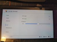
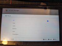
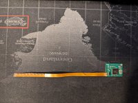
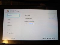
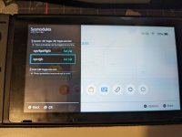
Sharing some progress on my WIP for picofly RGB bling... I'm planning to do a test install this weekend and will share some videos of the installed version once done.
Once fully tested I'll be putting everything up on git.
  • kicad RP2040 board + flex led strip (1010 RGBs - 1mm square).
  • sysmodule - monitor CPU load, temp etc & send data to RP2040 through I2C connection.
  • sysmodule also monitors stand-by / sleep of switch and turns leds off/on.
    (e.g. LEDs colour can be set show CPU load (VIBGYOR) - violet = low load -> red = high load)
  • App - configure mode for sysmodule.
  • Support for multiple led strips (maybe up-to 50 leds)
  • Updated firmware to support the above (mainly i2c mode after glitch).
 

Attachments

  • test.mp4
    2.8 MB
  • load.jpg
    load.jpg
    7.9 MB · Views: 22
  • modes.jpg
    modes.jpg
    3.7 MB · Views: 20
  • RP_flex.jpg
    RP_flex.jpg
    3.9 MB · Views: 17
  • settings.jpg
    settings.jpg
    3.4 MB · Views: 20
  • sysmodule.jpg
    sysmodule.jpg
    8.9 MB · Views: 18
  • sys-rgb app.jpg
    sys-rgb app.jpg
    6 MB · Views: 28

arvs

New Member
Newbie
Joined
Jul 24, 2023
Messages
4
Trophies
0
Age
36
XP
14
Country
New Zealand
Got this offer on a local craiglist:
View attachment 341370View attachment 341371 View attachment 341369

The seller says it's a new RP2040 Picofly based version modchip for Switch Lite and Oled, only.

What do you think about it, looks like it's a clearly fake, am I right?.. Or not?
It looks rather real than fake. That’s the truest picofly setup there is. Not the cleanest soldering nor the best wire used but if the person selling made it wor
Got this offer on a local craiglist:
View attachment 341370View attachment 341371 View attachment 341369

The seller says it's a new RP2040 Picofly based version modchip for Switch Lite and Oled, only.

What do you think about it, looks like it's a clearly fake, am I right?.. Or not?
That is the most real picofly installation in a sense. If they are faking it, they will put up a much better photo than that. Not the cleanest soldering job not even the most appropriate wire used but the person selling made it work (ofc you’re testing it before paying, right?)
 

Switxh

Well-Known Member
Member
Joined
Mar 11, 2023
Messages
110
Trophies
0
Age
28
XP
273
Country
United Kingdom
It looks rather real than fake. That’s the truest picofly setup there is. Not the cleanest soldering nor the best wire used but if the person selling made it wor

That is the most real picofly installation in a sense. If they are faking it, they will put up a much better photo than that. Not the cleanest soldering job not even the most appropriate wire used but the person selling made it work (ofc you’re testing it before paying, right?)
Check the date of the post you're replying to...
 

aleciobr

Member
Newcomer
Joined
Jun 27, 2023
Messages
22
Trophies
0
Age
32
XP
75
Country
Brazil
If all "unlock points" are calling normal then u would have a no sdcard screen;-)
Any point cannot be connected correct not just DAT 0.
Give us some picture to work with and the Morse code u get otherwise we can't help u.
Here
 

Attachments

  • Imagem do WhatsApp de 2023-07-28 à(s) 14.45.01.jpg
    Imagem do WhatsApp de 2023-07-28 à(s) 14.45.01.jpg
    204.5 KB · Views: 25
  • Vídeo do WhatsApp de 2023-07-28 à(s) 14.45.01.mp4
    6.9 MB

aleciobr

Member
Newcomer
Joined
Jun 27, 2023
Messages
22
Trophies
0
Age
32
XP
75
Country
Brazil
U do know how to read the morse code correct?

well anyway this is ur issue
=* D0 is not connected
i guess u have a dat0 adapter might wanna check that ,
also on the picture there is not much u can see from ur soldering job.............
on the diode scale it's giving 556 and without soldering it's giving 317
 

Attachments

  • Imagem do WhatsApp de 2023-07-28 à(1s) 15.42.35.jpg
    Imagem do WhatsApp de 2023-07-28 à(1s) 15.42.35.jpg
    199.5 KB · Views: 23
  • Imagem do WhatsApp de 2023-07-28 à(2s) 15.42.35.jpg
    Imagem do WhatsApp de 2023-07-28 à(2s) 15.42.35.jpg
    157.8 KB · Views: 19
  • Imagem do WhatsApp de 2023-07-28 à(s) 15.42.35.jpg
    Imagem do WhatsApp de 2023-07-28 à(s) 15.42.35.jpg
    225.6 KB · Views: 23

deeps

Well-Known Member
Member
Joined
Jul 3, 2007
Messages
454
Trophies
1
XP
1,272
Country
what would be the most appropriate method

There are three methods available that I would consider proper:

- Emmc Reball with 0.1mm enamel wire soldered to the dat0 point
- Green emmc adapter (works as a man-in-the-middle-sandwich between motherboard and emmc)
- layer drilling
 
  • Love
Reactions: Dee87

Switxh

Well-Known Member
Member
Joined
Mar 11, 2023
Messages
110
Trophies
0
Age
28
XP
273
Country
United Kingdom
on the diode scale it's giving 556 and without soldering it's giving 317
Looks to me like the adapter is tilted to the left. This would lift the contact away from the dat0 point. Adjust the adapter and apply tension on the right while you solder the legs in place. Tilting to the right slightly is fine but tilting to the right will result in poor connection. Putting the multi meter probe on the adapter to take a diode reading can apply enough tension to make a connection so it gives you false reassurance because you get reading but it's actually because the pressure from your probe is making the connection. When you remove the probe, the tension is removed and the connection is lost.
 

Hassal

Well-Known Member
Member
Joined
Apr 22, 2023
Messages
568
Trophies
0
Age
24
XP
515
Country
United Arab Emirates
Agree, and since drilling under layer D0 point now available, reballing eMMC seems less practical IMO.
I will have to disagree. Many already ruin their switches even scratching CLK point which is child's play and you're asking them to drill through layers to reach a point? I already foresee hundreds if not thousands of dead switches listed on ebay.
 

FreeLander

Well-Known Member
Member
Joined
Apr 6, 2023
Messages
350
Trophies
0
Age
35
XP
467
Country
United States
the entire dat0 slide-in-adapter method is damn useless and error prone. I wish someone hadn't come up with it so people would be forced to use proper methods.
Sweeter words have never been spoken.

I'm going on a Switch-killing spree till I get reballing right. I'm done with those adaptors.

Can't wait for my AMAOE kit
Post automatically merged:

I will have to disagree. Many already ruin their switches even scratching CLK point which is child's play and you're asking them to drill through layers to reach a point? I already foresee hundreds if not thousands of dead switches listed on ebay.
habibi, You're not on board with reballing nor drilling. Do you really enjoy using these adaptors?
 
  • Love
Reactions: QuiTim

jkyoho

Well-Known Member
Member
Joined
Sep 2, 2020
Messages
1,312
Trophies
0
Age
39
Location
TORONTO
Website
form.jotform.com
XP
2,255
Country
Canada
I will have to disagree. Many already ruin their switches even scratching CLK point which is child's play and you're asking them to drill through layers to reach a point? I already foresee hundreds if not thousands of dead switches listed on ebay.
HMM, interesting. I wish they are listed on eBay so I could save them from hell
 
  • Like
Reactions: Dee87

Dee87

Well-Known Member
Member
Joined
Mar 19, 2023
Messages
1,139
Trophies
1
XP
1,589
Country
Germany
HMM, interesting. I wish they are listed on eBay so I could save them from hell
hahahaha im the same , but the thing is most of those damaged board go from 100-150€ some i saw go for 200 insane prices Xd i dont understand why people pay so much for them
 
  • Like
Reactions: jkyoho

Site & Scene News

Popular threads in this forum

General chit-chat
Help Users
  • No one is chatting at the moment.
    a_username_that_isnt_cool @ a_username_that_isnt_cool: @Xdqwerty, about to