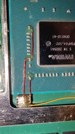
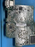
Theres possibility that it might not come from that, if nvidia tegra have something like internal voltage ref, and that pinout only used to add a capacitor on it.I believe somebody who reball the SOC itself can test in which soc pin that this caps is connected, and unfortunaltely i dont have access to that.
If i have to take a guess then it should be one of those.
It seems that number 2 is ground.
Anyone have a link for Tegra X1 pinout?
View attachment 379980
You are using an out of date browser. It may not display this or other websites correctly.
You should upgrade or use an alternative browser.
You should upgrade or use an alternative browser.
Staff Posts
Recent threadmarks
sharing files
Important Posts
Recent threadmarks
Firmwareswhat excatly do u need i do have donors where i can take the apus off of the boardI believe somebody who reball the SOC itself can test in which soc pin that this caps is connected, and unfortunaltely i dont have access to that.
If i have to take a guess then it should be one of those.
It seems that number 2 is ground.
Anyone have a link for Tegra X1 pinout?
View attachment 379980
but its gonna take till tonight or tommorow not sure when i have the time for it
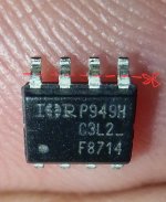
Here is a video of 8714 (same size). You have to cut the shield bridge to fit but I would suggest you cut 2/3 of the legs and solder to the side of the mosfet this way you don't risk scratching the board and I't might even fit under the shield without cutting anything because if you solder on the legs, the excess solder adds some height to the mosfet.Quick question. Has anyone recently had further experience with irf8736? Just got one, it's a chunky boy and I will fit a 1k pull down in the install but will have to trim the shield bridge but wanted to know any more info on people's experience with it.
And, does the aon7506 fit snug near the soc with out any need for trimming the metal seperating the ram and soc bit?
What do you recommend from an install and performance perspective between these two, seemingly, champ mosfets.
Appreciate it
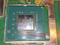
As for aon7560 it fits perfectly without any modifications (see pictures). I did add some solder mask as safety measure because you can never be too careful.
Attachments
Last edited by QuiTim,
That last pic, its just perfect.As for aon7560 it fits perfectly without any modifications (see pictures). I did add some solder mask as safety measure because you can never be too careful.

Post automatically merged:
what excatly do u need i do have donors where i can take the apus off of the board
but its gonna take till tonight or tommorow not sure when i have the time for it
With the soc detached and all pads are cleaned. Please measure these three point connect with which pin ( pins ? ).
Direct connection should be zero ohm.
My guess is point no 3 should connect with any pins which soldered on to G trace (but i can be wrong here).
Thanks to @QuiTim for the pic.
Last edited by cgtchy0412,
Same problem here.... do you have any pics of what look?sdcard circuit check if it has 3v on sdcard line, i've seen a switch with this specific issue, it's either the mosfet nearby that 3v or the driver.
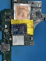
can this be done without replacing the LED?finally did one of these RP2040 installs; good learning experience after several years since my last SAMD21 install. went with a seeed xiao RP2040, dual mosfet. relocated the status LED to the front of the board where the (nearly) unused home button LED was, so it can act as an external status indicator. boot times seem good. quite pleased
View attachment 379924 View attachment 379925
View attachment 379927
Last edited by JaRocker,
LED how he do that????finally did one of these RP2040 installs; good learning experience after several years since my last SAMD21 install. went with a seeed xiao RP2040, dual mosfet. relocated the status LED to the front of the board where the (nearly) unused home button LED was, so it can act as an external status indicator. boot times seem good. quite pleased
View attachment 379924 View attachment 379925
View attachment 379927
- Joined
- Jul 12, 2010
- Messages
- 162
- Trophies
- 1
- Age
- 36
- Location
- Bananna Land.
- Website
- www.nerdfy.com.br
- XP
- 841
- Country

this is pornfinally did one of these RP2040 installs; good learning experience after several years since my last SAMD21 install. went with a seeed xiao RP2040, dual mosfet. relocated the status LED to the front of the board where the (nearly) unused home button LED was, so it can act as an external status indicator. boot times seem good. quite pleased
View attachment 379924 View attachment 379925
View attachment 379927
 . Please read the rules of GBATEMP before posting.
the site is a tech porn site so it's finethis is porn. Please read the rules of GBATEMP before posting.
They explained how a few pages back, after their initial post.LED how he do that????
I completely removed the home button LED; it was originally on the two pads on the right side of where the RP2040's status LED is now. the top pad is constant 3.3V, which is convenient as the status LED needs that as well. the bottom pad is a switched ground to control the original home button LED; I repurposed this to break out and connect the data line of the status LED. I then manually ran a ground wire directly to the status LED. in the extremely unlikely event that nintendo further utilizes the notification feature and the home button LED "turns on" with my status LED in place, no ill should happen, as it would only be grounding the data in pin while the status LED is not in use.
can this be done without replacing the LED?
perhaps; maybe by mounting the status LED further away, perpendicular to the motherboard, such that it is casting its light into the side of the translucent cover, instead of resting under it and casting upward. hopefully that would still diffuse it enough to be evenly lit. I had done something similar with the status LED of my SAMD21 installs on the original switch using the light sensor, where it cast into the side of the sensor's light pipe. if I do another install I will play around with other solutions
RST line is checked whether the voltage between 1.6-2.0v. Outside than that throws error RST disconnected.I have an oled here that continues to says that RST is not connect. It is very much connected. Any thoughts?
Mine is at 1.3. How do I fix it?RST line is checked whether the voltage between 1.6-2.0v. Outside than that throws error RST disconnected.
As the comment is. Check the mosfet.Someone can explain me this error :
==* CPU always reach BCT check (no glitch reaction, check mosfet)
The emmc stage is good, the glitch executed via 'cpu pin', but theres no response.
Check the mosfet, maybe the 'cpu pin' connection with the G of mosfet is disconnected. Or maybe the D of mosfet is not connected. Check the resistance between the D and GND, the good value is around 10-60ohms.
Post automatically merged:
I suspect theres some short in somewhere.Mine is at 1.3. How do I fix it?
Ok that line or just somewhere in general?As the comment is. Check the mosfet.
The emmc stage is good, the glitch executed via 'cpu pin', but theres no response.
Check the mosfet, maybe the 'cpu pin' connection with the G of mosfet is disconnected. Or maybe the D of mosfet is not connected. Check the resistance between the D and GND, the good value is around 10-60ohms.
Post automatically merged:
I suspect theres some short in somewhere.
Hello,
Just to make sure I got a full uf2 file, I ran a hex comparison between Github's and Rehus's 2.73 files and found differences, I'm guessing maybe because it was changed to pdf? (renamed it). Which version to use would you use, @rehius? <3
Just to make sure I got a full uf2 file, I ran a hex comparison between Github's and Rehus's 2.73 files and found differences, I'm guessing maybe because it was changed to pdf? (renamed it). Which version to use would you use, @rehius? <3
Attachments
A lot of this may have to do with how you download from github as well.Hello,
Just to make sure I got a full uf2 file, I ran a hex comparison between Github's and Rehus's 2.73 files and found differences, I'm guessing maybe because it was changed to pdf? (renamed it). Which version to use would you use, @rehius? <3
Some people right-click and hit save as, and I believe this is the method people have issue with.
Click the link, then click "Download" to the right and I think that gets the correct file.
Similar threads
- Replies
- 4
- Views
- 2K
- Replies
- 2
- Views
- 680
- Replies
- 42
- Views
- 7K
Site & Scene News
New Hot Discussed
-
-
31K views
New static recompiler tool N64Recomp aims to seamlessly modernize N64 games
As each year passes, retro games become harder and harder to play, as the physical media begins to fall apart and becomes more difficult and expensive to obtain. The... -
27K views
Nintendo officially confirms Switch successor console, announces Nintendo Direct for next month
While rumors had been floating about rampantly as to the future plans of Nintendo, the President of the company, Shuntaro Furukawa, made a brief statement confirming... -
24K views
TheFloW releases new PPPwn kernel exploit for PS4, works on firmware 11.00
TheFlow has done it again--a new kernel exploit has been released for PlayStation 4 consoles. This latest exploit is called PPPwn, and works on PlayStation 4 systems... -
24K views
Name the Switch successor: what should Nintendo call its new console?
Nintendo has officially announced that a successor to the beloved Switch console is on the horizon. As we eagerly anticipate what innovations this new device will... -
14K views
DOOM has been ported to the retro game console in Persona 5 Royal
DOOM is well-known for being ported to basically every device with some kind of input, and that list now includes the old retro game console in Persona 5 Royal... -
12K views
Delta emulator for iOS will support iPad devices in its next update
With just a couple weeks after its initial release in the App Store, the Delta emulator for iOS was received with great success, after Apple loosened up its rules in...by ShadowOne333 36 -
12K views
Mario Builder 64 is the N64's answer to Super Mario Maker
With the vast success of Super Mario Maker and its Switch sequel Super Mario Maker 2, Nintendo fans have long been calling for "Maker" titles for other iconic genres... -
12K views
Anbernic reveals the RG35XXSP, a GBA SP-inspired retro handheld
Retro handheld manufacturer Anbernic has revealed its first clamshell device: the Anbernic RG35XXSP. As the suffix indicates, this handheld's design is inspired by... -
11K views
"Nintendo World Championships: NES Edition", a new NES Remix-like game, launching July 18th
After rumour got out about an upcoming NES Edition release for the famed Nintendo World Championships, Nintendo has officially unveiled the new game, titled "Nintendo...by ShadowOne333 78 -
11K views
Microsoft is closing down several gaming studios, including Tango Gameworks and Arkane Austin
The number of layoffs and cuts in the videogame industry sadly continue to grow, with the latest huge layoffs coming from Microsoft, due to what MIcrosoft calls a...by ShadowOne333 65
-
-
-
312 replies
Name the Switch successor: what should Nintendo call its new console?
Nintendo has officially announced that a successor to the beloved Switch console is on the horizon. As we eagerly anticipate what innovations this new device will...by Costello -
233 replies
Nintendo officially confirms Switch successor console, announces Nintendo Direct for next month
While rumors had been floating about rampantly as to the future plans of Nintendo, the President of the company, Shuntaro Furukawa, made a brief statement confirming...by Chary -
136 replies
New static recompiler tool N64Recomp aims to seamlessly modernize N64 games
As each year passes, retro games become harder and harder to play, as the physical media begins to fall apart and becomes more difficult and expensive to obtain. The...by Chary -
96 replies
Ubisoft reveals 'Assassin's Creed Shadows' which is set to launch later this year
Ubisoft has today officially revealed the next installment in the Assassin's Creed franchise: Assassin's Creed Shadows. This entry is set in late Sengoku-era Japan...by Prans -
88 replies
The Kingdom Hearts games are coming to Steam
After a little more than three years of exclusivity with the Epic Games Store, Square Enix has decided to bring their beloved Kingdom Hearts franchise to Steam. The...by Chary -
80 replies
TheFloW releases new PPPwn kernel exploit for PS4, works on firmware 11.00
TheFlow has done it again--a new kernel exploit has been released for PlayStation 4 consoles. This latest exploit is called PPPwn, and works on PlayStation 4 systems...by Chary -
78 replies
"Nintendo World Championships: NES Edition", a new NES Remix-like game, launching July 18th
After rumour got out about an upcoming NES Edition release for the famed Nintendo World Championships, Nintendo has officially unveiled the new game, titled "Nintendo...by ShadowOne333 -
71 replies
DOOM has been ported to the retro game console in Persona 5 Royal
DOOM is well-known for being ported to basically every device with some kind of input, and that list now includes the old retro game console in Persona 5 Royal...by relauby -
71 replies
Majora’s Mask PC port 2Ship2Harkinian gets its first release
After several months of work, the Harbour Masters 64 team have released their first public build of 2Ship2Harkinian, a feature-rich Majora's Mask PC port. This comes...by Scarlet -
65 replies
Microsoft is closing down several gaming studios, including Tango Gameworks and Arkane Austin
The number of layoffs and cuts in the videogame industry sadly continue to grow, with the latest huge layoffs coming from Microsoft, due to what MIcrosoft calls a...by ShadowOne333
-
Popular threads in this forum
General chit-chat
- No one is chatting at the moment.
-
 @
Psionic Roshambo:
You just need to get older it takes time to go from "I'd hit that" meaning sex to "I'd hit that... With my car" thinking about your ex.+1
 -
-
-
-
-
-
 @
Psionic Roshambo:
I think I have convinced them that multiplexing a polarized Lazer for fiber optic networking is a good idea lol
 -
-
-
-
-
-
-
-
 @
a_username_that_is_cool:
Happy early birthday (we need a word for the day before someones birthday)+1
 -
-
-
-
-
-
-
-
-
-


