Around $4 AUD for letter postage. This batch will be made in China, but either way express post gets them from Gerber files to my house in 5 business daysCool, what's the postage to UK like and lead time compared to China?
You are using an out of date browser. It may not display this or other websites correctly.
You should upgrade or use an alternative browser.
You should upgrade or use an alternative browser.
Staff Posts
Recent threadmarks
sharing files
Important Posts
Recent threadmarks
Firmwaresbecause cut 3v3?Going to chime in and say this is all I do with the ODAT0 adapters I get.
I literally just snip the left hand piece off.
Job done!
because cut 3v3?
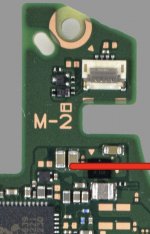
My 3.3v comes from here...
Attachments
yes, but cutting that side fits better under emmc?My 3.3v comes from here...
Post automatically merged:
I've heard that those adapters give problems
Mosfets is on the pcb?Around $4 AUD for letter postage. This batch will be made in China, but either way express post gets them from Gerber files to my house in 5 business days
hi guys, can they follow some procedure for this?Yesterday I did several installations.
Among these is a dispute that I don't know how it works (after replacing the display) despite the bent mainboard.
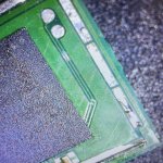
There is also an oled made with Reballing, if it can serve for some ideas, I also used new connections for the mosfet.
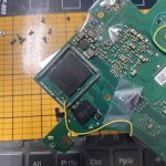
Photo release (The photos are mixed up).
I'm continuing to use FW 2.67 which in my opinion is fast, stable, reliable. What am I getting into by not using the new FW?
Post automatically merged:
As for this problem, I carried out the unbrick level 1 and 2 procedures, after adding resistors (actually I redid the whole installation (the one carried out by the customer independently was disastrous by my standards).
Now I don't get slow memory error anymore, and in emummc everything works, even waking up.
I can't get into OFW though, after the black screen nintendo logo.
What guides can I follow?
I can download the keys without error, it takes like 190 or so.
Yes, we discussed the same texas instruments mosfet the other dayMosfets is on the pcb?
Do you have link on unbrick level 1 and level 2?hi guys, can they follow some procedure for this?
sthetix video's from youtubeDo you have link on unbrick level 1 and level 2?
Post automatically merged:
I don't understand why it works in emummc, and i don't ofwsthetix video's from youtube
Solder mask is applied to the board to prevent solder from sticking during manufacturing where they don't want it to stick. If there is solder mask on any test pads or whatever you want to solder to, you need to carefully scrape it away first. Here is somebody doing it on an old Atari 2600. You need to be quite careful on a more delicate console like the Switch that has very small pads and traces.i dont think so ive scrapped any green mask nor im aware of it ????..can you put some light on what is green mask is it to be removed or not ??? regards
What techniques are people here using to remove solder mask from test points before soldering?
So an update. New adaptor arrived. Installed it. Now the switch is blackscreen on boot and the picofly still flashes sometimes =* and sometimes ==*. Before the new adaptor it booted into OFW no issues. Sigh.Yeah the old one isn't viable now, one of the ground 'legs' tore when I tried to desolder it to make the changeThe newer 4 anchor point one is hitting my mailbox any day now so I'll just use that. Thanks!
Any ideas? I'm about to give up and send it to a repair shop.
I got =* on my OLED when I used a DAT0 adapter but once I pushed it in further it worked. Sometimes it seems connected when you take a diode reading cus the pressure from your probe slightly moves the adapter but it may not be connected when you remove the probe. Even with anchors soldered. That's what I experienced anyway. I would reseat the DAT0 adapter. It could also have debris or flux under the EMMC. I like to use ultrasonic baths because flux can carry dust and debris under the BGA chips.So an update. New adaptor arrived. Installed it. Now the switch is blackscreen on boot and the picofly still flashes sometimes =* and sometimes ==*. Before the new adaptor it booted into OFW no issues. Sigh.
Any ideas? I'm about to give up and send it to a repair shop.
And that could also make the black screen? It doesn't even boot to OFW now even after removing the new DAT0I got =* on my OLED when I used a DAT0 adapter but once I pushed it in further it worked. Sometimes it seems connected when you take a diode reading cus the pressure from your probe slightly moves the adapter but it may not be connected when you remove the probe. Even with anchors soldered. That's what I experienced anyway. I would reseat the DAT0 adapter. It could also have debris or flux under the EMMC. I like to use ultrasonic baths because flux can carry dust and debris under the BGA chips.
Check there is no bridges on the capacitors on the CPU for black screen and also check CMD resistor and solder joint.And that could also make the black screen? It doesn't even boot to OFW now even after removing the new DAT0
When you check using diode mode value to the D0 test point in the adapter, what is the measurement?So an update. New adaptor arrived. Installed it. Now the switch is blackscreen on boot and the picofly still flashes sometimes =* and sometimes ==*. Before the new adaptor it booted into OFW no issues. Sigh.
Any ideas? I'm about to give up and send it to a repair shop.
Much thanks! I’ve ordered the set to hopefully up my reballing game.@karatefeet made a request for links to 'what I use for reballing', figured I'd share with the class...
I just bought the magnetic base, positioning plate and BGA153 stencil from this link:
https://a.aliexpress.com/_mO67mrS
1st time using a mag base and fixture, gotta say, im never going back.
Post automatically merged:
Any tips using the stencil? I have a thin one and one for direct heating and still fail at reballing the eMMC. Specifically I have a hard time getting the stencil off the chip. Using mechanic solder paste which should be good quality.na bro im good with my stencil , why should i spend money on something that i already have doesnt work better or worse then what i use so just a waste of money for me Xd
Post automatically merged:
wooooooow that install looks horrible i hope u gave that thing a nice reinstall
Post automatically merged:
Would you have a link for good dat0 adapters? Tried ones from Ali yesterday and could not get a diode reading at all.When i dont use high quality cpu flex cables I always prefer dual mosfets with pulldown resistor. Better safe than sorry. And about the dat0 adapters i guarantee you that if you find the good ones and install them correctly they will work for years to come.
Last edited by karatefeet,
i have used stencil for old samsung s4 i9505.Much thanks! I’ve ordered the set to hopefully up my reballing game.
Post automatically merged:
Any tips using the stencil? I have a thin one and one for direct heating and still fail at reballing the eMMC. Specifically I have a hard time getting the stencil off the chip. Using mechanic solder paste which should be good quality.
Post automatically merged:
Would you have a link for good dat0 adapters? Tried ones from Ali yesterday and could not get a diode reading at all.
click here
Yeah most important thing is get some height around the emmc so its level with the emmc I use magnets and double sided tape under the emmc so it level with the magnet around.Much thanks! I’ve ordered the set to hopefully up my reballing game.
Post automatically merged:
Any tips using the stencil? I have a thin one and one for direct heating and still fail at reballing the eMMC. Specifically I have a hard time getting the stencil off the chip. Using mechanic solder paste which should be good quality.
Post automatically merged:
Would you have a link for good dat0 adapters? Tried ones from Ali yesterday and could not get a diode reading at all.
The add ur solder paste , make sure the stencil has a even amount of solder paste.
When ur done put pressure on the middle of the emmc stencil so its doesn't warp when heated.
Then heat it till u having shinny balls let it cool down but keep pressure on the stencil.
Then u should be able to take it slowly off if its still sticking add some isoprop oder heat it up an bit with some flux and tilt it slowly till it comes off
Solder mask is applied to the board to prevent solder from sticking during manufacturing where they don't want it to stick. If there is solder mask on any test pads or whatever you want to solder to, you need to carefully scrape it away first. Here is somebody doing it on an old Atari 2600. You need to be quite careful on a more delicate console like the Switch that has very small pads and traces.
What techniques are people here using to remove solder mask from test points before soldering?
you guys remove solder mask before installing picofly on switch??? i havent seen anyone doing in tutorials available correct me if im wrong
Similar threads
- Replies
- 4
- Views
- 2K
- Replies
- 2
- Views
- 630
- Replies
- 42
- Views
- 7K
Site & Scene News
New Hot Discussed
-
-
28K views
New static recompiler tool N64Recomp aims to seamlessly modernize N64 games
As each year passes, retro games become harder and harder to play, as the physical media begins to fall apart and becomes more difficult and expensive to obtain. The... -
25K views
Nintendo officially confirms Switch successor console, announces Nintendo Direct for next month
While rumors had been floating about rampantly as to the future plans of Nintendo, the President of the company, Shuntaro Furukawa, made a brief statement confirming... -
23K views
TheFloW releases new PPPwn kernel exploit for PS4, works on firmware 11.00
TheFlow has done it again--a new kernel exploit has been released for PlayStation 4 consoles. This latest exploit is called PPPwn, and works on PlayStation 4 systems... -
22K views
Nintendo takes down Gmod content from Steam's Workshop
Nintendo might just as well be a law firm more than a videogame company at this point in time, since they have yet again issued their now almost trademarked usual...by ShadowOne333 129 -
21K views
Name the Switch successor: what should Nintendo call its new console?
Nintendo has officially announced that a successor to the beloved Switch console is on the horizon. As we eagerly anticipate what innovations this new device will... -
17K views
A prototype of the original "The Legend of Zelda" for NES has been found and preserved
Another video game prototype has been found and preserved, and this time, it's none other than the game that spawned an entire franchise beloved by many, the very...by ShadowOne333 32 -
14K views
DOOM has been ported to the retro game console in Persona 5 Royal
DOOM is well-known for being ported to basically every device with some kind of input, and that list now includes the old retro game console in Persona 5 Royal... -
12K views
AYANEO officially launches the Pocket S, its next-generation Android gaming handheld
Earlier this year, AYANEO revealed details of its next Android-based gaming handheld, the AYANEO Pocket S. However, the actual launch of the device was unknown; that... -
11K views
Delta emulator for iOS will support iPad devices in its next update
With just a couple weeks after its initial release in the App Store, the Delta emulator for iOS was received with great success, after Apple loosened up its rules in...by ShadowOne333 35 -
11K views
Anbernic reveals the RG35XXSP, a GBA SP-inspired retro handheld
Retro handheld manufacturer Anbernic has revealed its first clamshell device: the Anbernic RG35XXSP. As the suffix indicates, this handheld's design is inspired by...
-
-
-
293 replies
Name the Switch successor: what should Nintendo call its new console?
Nintendo has officially announced that a successor to the beloved Switch console is on the horizon. As we eagerly anticipate what innovations this new device will...by Costello -
232 replies
Nintendo officially confirms Switch successor console, announces Nintendo Direct for next month
While rumors had been floating about rampantly as to the future plans of Nintendo, the President of the company, Shuntaro Furukawa, made a brief statement confirming...by Chary -
133 replies
New static recompiler tool N64Recomp aims to seamlessly modernize N64 games
As each year passes, retro games become harder and harder to play, as the physical media begins to fall apart and becomes more difficult and expensive to obtain. The...by Chary -
129 replies
Nintendo takes down Gmod content from Steam's Workshop
Nintendo might just as well be a law firm more than a videogame company at this point in time, since they have yet again issued their now almost trademarked usual...by ShadowOne333 -
95 replies
Ubisoft reveals 'Assassin's Creed Shadows' which is set to launch later this year
Ubisoft has today officially revealed the next installment in the Assassin's Creed franchise: Assassin's Creed Shadows. This entry is set in late Sengoku-era Japan...by Prans -
87 replies
The Kingdom Hearts games are coming to Steam
After a little more than three years of exclusivity with the Epic Games Store, Square Enix has decided to bring their beloved Kingdom Hearts franchise to Steam. The...by Chary -
80 replies
TheFloW releases new PPPwn kernel exploit for PS4, works on firmware 11.00
TheFlow has done it again--a new kernel exploit has been released for PlayStation 4 consoles. This latest exploit is called PPPwn, and works on PlayStation 4 systems...by Chary -
78 replies
"Nintendo World Championships: NES Edition", a new NES Remix-like game, launching July 18th
After rumour got out about an upcoming NES Edition release for the famed Nintendo World Championships, Nintendo has officially unveiled the new game, titled "Nintendo...by ShadowOne333 -
71 replies
DOOM has been ported to the retro game console in Persona 5 Royal
DOOM is well-known for being ported to basically every device with some kind of input, and that list now includes the old retro game console in Persona 5 Royal...by relauby -
65 replies
Microsoft is closing down several gaming studios, including Tango Gameworks and Arkane Austin
The number of layoffs and cuts in the videogame industry sadly continue to grow, with the latest huge layoffs coming from Microsoft, due to what MIcrosoft calls a...by ShadowOne333
-
Popular threads in this forum
General chit-chat
- No one is chatting at the moment.
-
-
-
-
-
-
-
-
-
-
-
-
-
-
-
-
-
-
-
 @
SenorED:
jkkkkkkkkkkkkkkkkkkkkkkkkkkkkkkkkkkk https://www.youtube.com/watch?v=2ryWgzW4RLI&ab_channel=MarioBendor'sComentario
kkkkkkkkkkkkkkkkkkkkkkkkkkkkkkkkk -
-
-
-
-
-


