You are using an out of date browser. It may not display this or other websites correctly.
You should upgrade or use an alternative browser.
You should upgrade or use an alternative browser.
Staff Posts
Recent threadmarks
sharing files
Important Posts
Recent threadmarks
FirmwaresWhat is the alternative GND point on V2 instead of the point at capacitor near M92T36 IC? I have seen that there are many gnd point on mobo in v6.2 guide
I might forgot, but in my memory i use that point.
I did the research and found on old topic that have this ground point. It look safer and easier than the point on V6.2 guideView attachment 377616
I might forgot, but in my memory i use that point.
na bro im good with my stencil , why should i spend money on something that i already have doesnt work better or worse then what i use so just a waste of money for me Xd
Post automatically merged:
wooooooow that install looks horrible i hope u gave that thing a nice reinstallI did the research and found on old topic that have this ground point. It look safer and easier than the point on V6.2 guideView attachment 377623
Last edited by Dee87,
you installed the picofly chip in your v2 switch its working fine or you attempting to install it again?I did the research and found on old topic that have this ground point. It look safer and easier than the point on V6.2 guideView attachment 377623
this's not my installation, its someone else. I have seen this installation use alternative 3.3v point and gnd point different from the picture on V6 guide. It avoid using the point near M92T36 IC that reduce the failure chance. It will help me improve the next installation and avoid my mistake on the last installationna bro im good with my stencil , why should i spend money on something that i already have doesnt work better or worse then what i use so just a waste of money for me Xd
Post automatically merged:
wooooooow that install looks horrible i hope u gave that thing a nice reinstall
Post automatically merged:
I installed the picofly successfully on my v2 and its working fine but i almost break the capacitor near M92T36 IC ( you can see it in few previous page). I need to take note some alternative safer point i can get to reduce the failureyou installed the picofly chip in your v2 switch its working fine or you attempting to install it again?
the ground point u can can take from any shielding or any grounded unused pad , there are plenty of them on all boards i wouldnt recommend using the ones on the caps since its hard for unexperienced people to solder to without bridging anything else.this's not my installation, its someone else. I have seen this installation use alternative 3.3v point and gnd point different from the picture on V6 guide. It avoid using the point near M92T36 IC that reduce the failure chance. It will help me improve the next installation and avoid my mistake on the last installation
Post automatically merged:
I installed the picofly successfully on my v2 and its working fine but i almost break the capacitor near M92T36 IC ( you can see it in few previous page). I need to take note some alternative safer point i can get to reduce the failure
i think at @lightninjay should point out to a different gnd point in his .pdf guide :-) just a small hint @lightninjay no hate bro
would you recommend a safe ground point to me as well as alternate...im.having a microscope as well to work only issue im facing is while installing picofly in my switch v1 patched solder not sticking to switch motherboard points especially dat rst etcthis's not my installation, its someone else. I have seen this installation use alternative 3.3v point and gnd point different from the picture on V6 guide. It avoid using the point near M92T36 IC that reduce the failure chance. It will help me improve the next installation and avoid my mistake on the last installation
Post automatically merged:
I installed the picofly successfully on my v2 and its working fine but i almost break the capacitor near M92T36 IC ( you can see it in few previous page). I need to take note some alternative safer point i can get to reduce the failure
can you show me some alternative gnd point? my knowledge of electronics is humble (above zero a little bit). thanks!the ground point u can can take from any shielding or any grounded unused pad , there are plenty of them on all boards i wouldnt recommend using the ones on the caps since its hard for unexperienced people to solder to without bridging anything else.
i think at @lightninjay should point out to a different gnd point in his .pdf guide :-) just a small hint @lightninjay no hate bro
Post automatically merged:
would you recommend a safe ground point to me as well as alternate...im.having a microscope as well to work only issue im facing is while installing picofly in my switch v1 patched solder not sticking to switch motherboard points especially dat rst etc
Im learning too. For unstick pad, i think you can add some flux on it and try to tin it gently. It will hard at begin but after 4-5 time trying to tin the pad, the lead will stick on. Or you can try to scratch it gently, the copper will be show and easy to tin it ( I dont recommend this method because it can damage the pad and rip it off)would you recommend a safe ground point to me as well as alternate...im.having a microscope as well to work only issue im facing is while installing picofly in my switch v1 patched solder not sticking to switch motherboard points especially dat rst etc
Last edited by Browbon,
the ground point u can can take from any shielding or any grounded unused pad , there are plenty of them on all boards i wouldnt recommend using the ones on the caps since its hard for unexperienced people to solder to without bridging anything else.
i think at @lightninjay should point out to a different gnd point in his .pdf guide :-) just a small hint @lightninjay no hate bro
True but if they can't manage a small ground how are they going to manage the rest of the points. This isn't exactly an easy mod to do, but yeah maybe there is a larger gnd pad we can use on board
Hello there, after reading a bit, is the pull-down resistor mandatory on the mosfet and what are the risk of not doing it ? I've done 2 dual-mosfet install without issue but i'm worried after reading these posts x)
Thare are plenty enough larger point :-)True but if they can't manage a small ground how are they going to manage the rest of the points. This isn't exactly an easy mod to do, but yeah maybe there is a larger gnd pad we can use on board
I'm sure there are, I just cbf doing the hard work XDThare are plenty enough larger point :-)
I havent done any install as long as u don't disconnect the CPU while on there shouldn't be a issue.Hello there, after reading a bit, is the pull-down resistor mandatory on the mosfet and what are the risk of not doing it ? I've done 2 dual-mosfet install without issue but i'm worried after reading these posts x)
Nope. This is something I said from the very beginning when I called out a GND point in the guide at ALL.the ground point u can can take from any shielding or any grounded unused pad , there are plenty of them on all boards i wouldnt recommend using the ones on the caps since its hard for unexperienced people to solder to without bridging anything else.
i think at @lightninjay should point out to a different gnd point in his .pdf guide :-) just a small hint @lightninjay no hate bro
"Lightninjay, why would you tell people a specific point to solder GND? There are SOOOO MANY other better points?"
Me:"Because people need to be told what to do."
If someone is incapable of making such a trivial choice as where to solder GND, or don't understand the significance of what GND is to a functioning circuit, then as far as I'm concerned, they can go kick rocks and shouldn't be doing this mod.
I even went so far as to callout a place to solder GND AND say that you can use ANY other GND on the board.
The GND points in the guide will not be changed.
DragonFly
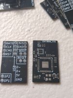
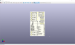
Just got my dragonFly boards in, I'll let you guys know how they go
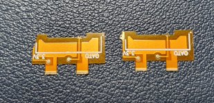
Also I made some changes and have ordered some to be assembled. If everything goes well you guys can have some to test.


Just got my dragonFly boards in, I'll let you guys know how they go
Also I made some changes and have ordered some to be assembled. If everything goes well you guys can have some to test.
- Dual MOSFET onboard in single package
- CMOS oscillator
- All components are virtually the smallest available package size
- Ideally would be made of 0.1mm flex, but 0.8mm/1mm FR4 is cheap and good enough for this revision
- 22mmx13mm(7/8"x1/2"), final version will be 15mmx10mm(5/8"x3/8")
- I think I'll sell them for $15 AUD ($10 USD)
- Most importantly, rounded traces
Attachments
Last edited by CodyRoseman,
DragonFly
Just got my dragonFly boards in, I'll let you guys know how they go
Also I made some changes and have ordered some to be assembled. If everything goes well you guys can have some to test.
View attachment 377641View attachment 377639
- Dual MOSFET onboard in single package
- CMOS oscillator
- All components are virtually the smallest available package size
- Ideally would be made of 0.1mm flex, but 0.8mm/1mm FR4 is cheap and good enough for this revision
- 22mmx13mm(7/8"x1/2"), final version will be 15mmx10mm(5/8"x3/8")
- I think I'll sell them for $15 AUD ($10 USD)
Cool, what's the postage to UK like and lead time compared to China?
Similar threads
- Replies
- 4
- Views
- 2K
- Replies
- 2
- Views
- 635
- Replies
- 42
- Views
- 7K
Site & Scene News
New Hot Discussed
-
-
29K views
New static recompiler tool N64Recomp aims to seamlessly modernize N64 games
As each year passes, retro games become harder and harder to play, as the physical media begins to fall apart and becomes more difficult and expensive to obtain. The... -
25K views
Nintendo officially confirms Switch successor console, announces Nintendo Direct for next month
While rumors had been floating about rampantly as to the future plans of Nintendo, the President of the company, Shuntaro Furukawa, made a brief statement confirming... -
23K views
TheFloW releases new PPPwn kernel exploit for PS4, works on firmware 11.00
TheFlow has done it again--a new kernel exploit has been released for PlayStation 4 consoles. This latest exploit is called PPPwn, and works on PlayStation 4 systems... -
22K views
Nintendo takes down Gmod content from Steam's Workshop
Nintendo might just as well be a law firm more than a videogame company at this point in time, since they have yet again issued their now almost trademarked usual...by ShadowOne333 129 -
21K views
Name the Switch successor: what should Nintendo call its new console?
Nintendo has officially announced that a successor to the beloved Switch console is on the horizon. As we eagerly anticipate what innovations this new device will... -
17K views
A prototype of the original "The Legend of Zelda" for NES has been found and preserved
Another video game prototype has been found and preserved, and this time, it's none other than the game that spawned an entire franchise beloved by many, the very...by ShadowOne333 32 -
14K views
DOOM has been ported to the retro game console in Persona 5 Royal
DOOM is well-known for being ported to basically every device with some kind of input, and that list now includes the old retro game console in Persona 5 Royal... -
12K views
AYANEO officially launches the Pocket S, its next-generation Android gaming handheld
Earlier this year, AYANEO revealed details of its next Android-based gaming handheld, the AYANEO Pocket S. However, the actual launch of the device was unknown; that... -
11K views
Delta emulator for iOS will support iPad devices in its next update
With just a couple weeks after its initial release in the App Store, the Delta emulator for iOS was received with great success, after Apple loosened up its rules in...by ShadowOne333 35 -
11K views
Anbernic reveals the RG35XXSP, a GBA SP-inspired retro handheld
Retro handheld manufacturer Anbernic has revealed its first clamshell device: the Anbernic RG35XXSP. As the suffix indicates, this handheld's design is inspired by...
-
-
-
294 replies
Name the Switch successor: what should Nintendo call its new console?
Nintendo has officially announced that a successor to the beloved Switch console is on the horizon. As we eagerly anticipate what innovations this new device will...by Costello -
232 replies
Nintendo officially confirms Switch successor console, announces Nintendo Direct for next month
While rumors had been floating about rampantly as to the future plans of Nintendo, the President of the company, Shuntaro Furukawa, made a brief statement confirming...by Chary -
133 replies
New static recompiler tool N64Recomp aims to seamlessly modernize N64 games
As each year passes, retro games become harder and harder to play, as the physical media begins to fall apart and becomes more difficult and expensive to obtain. The...by Chary -
129 replies
Nintendo takes down Gmod content from Steam's Workshop
Nintendo might just as well be a law firm more than a videogame company at this point in time, since they have yet again issued their now almost trademarked usual...by ShadowOne333 -
95 replies
Ubisoft reveals 'Assassin's Creed Shadows' which is set to launch later this year
Ubisoft has today officially revealed the next installment in the Assassin's Creed franchise: Assassin's Creed Shadows. This entry is set in late Sengoku-era Japan...by Prans -
87 replies
The Kingdom Hearts games are coming to Steam
After a little more than three years of exclusivity with the Epic Games Store, Square Enix has decided to bring their beloved Kingdom Hearts franchise to Steam. The...by Chary -
80 replies
TheFloW releases new PPPwn kernel exploit for PS4, works on firmware 11.00
TheFlow has done it again--a new kernel exploit has been released for PlayStation 4 consoles. This latest exploit is called PPPwn, and works on PlayStation 4 systems...by Chary -
78 replies
"Nintendo World Championships: NES Edition", a new NES Remix-like game, launching July 18th
After rumour got out about an upcoming NES Edition release for the famed Nintendo World Championships, Nintendo has officially unveiled the new game, titled "Nintendo...by ShadowOne333 -
71 replies
DOOM has been ported to the retro game console in Persona 5 Royal
DOOM is well-known for being ported to basically every device with some kind of input, and that list now includes the old retro game console in Persona 5 Royal...by relauby -
65 replies
Microsoft is closing down several gaming studios, including Tango Gameworks and Arkane Austin
The number of layoffs and cuts in the videogame industry sadly continue to grow, with the latest huge layoffs coming from Microsoft, due to what MIcrosoft calls a...by ShadowOne333
-
Popular threads in this forum
General chit-chat
- No one is chatting at the moment.
-
-
-
-
-
-
-
-
-
-
-
-
-
-
-
-
-
-
 @
SenorED:
jkkkkkkkkkkkkkkkkkkkkkkkkkkkkkkkkkkk https://www.youtube.com/watch?v=2ryWgzW4RLI&ab_channel=MarioBendor'sComentario
kkkkkkkkkkkkkkkkkkkkkkkkkkkkkkkkk -
-
-
-
-
-
-


