Hacking Hardware Picofly - a HWFLY switch modchip

floxcap

Well-Known Member
Newcomer
Joined
May 21, 2023
Messages
69
Trophies
0
XP
281
Country
Australia
Great work. I'm gonna go ahead a try to figure out how to order a couple of these from JLCPCb.
Thank you for sharing this
Cost wise - it would make the most sense to make a bulk order... There's a minimum cost JLC charge for "setup" fees and shipping.

For an order of their minimum (5 units) it works out "expensive"... but the more boards ordered the more the base fees are spread across each unit (hope that makes sense).

Also stocking the components in bulk reduces the cost.
e.g for 10x RP2040 at JLC it's $1.36 AU but for 100x it's $1.08 AU (the RP2040 is the most "expensive" component on the board).

A decent order would make the unit price less than what I've seen for the tiny board.
 
  • Like
Reactions: QuiTim

NooBziN

Well-Known Member
Member
Joined
Apr 28, 2016
Messages
176
Trophies
0
Age
38
XP
458
Country
Brazil
@NooBziN Your "rainbow" installations have become famous :D
Post automatically merged:


Yep, thats the shitty one unfortunately, the one that has been giving everybody here hard time
how can this
I will ask for image rights :rofl2:
Post automatically merged:

Aliexpress is selling ptfe wire and using her/his mod installation as advertising picture :D
that's why I left the watermark phone model
 
  • Like
  • Haha
Reactions: Danook28 and QuiTim

Danook28

Well-Known Member
Member
Joined
Jul 17, 2018
Messages
502
Trophies
0
Age
34
XP
1,050
Country
Oman
It appears as though they are intentionally shifting the adapter to the side which includes a pin that is hooked to nothing. This was discussed as a potential option earlier in the thread, but is still a messy and unreliable option.

Either get a better adapter, or set a permanent DAT0, as @Dee87 frequently suggests. But do NOT install shitty OATO adapters and then ask here why things aren't working, when you likely shorted the DAT0 on your/your customer's OLED and now have a headache of a recovery process ahead of you.
I never use this i buy orginal stuff only brother thanks for info..
 

poiu15

Member
Newcomer
Joined
Apr 22, 2023
Messages
14
Trophies
0
Age
29
XP
69
Country
Afghanistan


He use dat0 adapter same that i was add pic before. And it is not bridge how that work with him perfect job.

The dat0 adapter he used is still defective. It will shortcircuit adjacent pins. From the view point of the video, the dat1 pin is on the left side of dat0, on the right side of dat0, is a NC pin, which is not used. He shifted the dat0 adapter to the right side, it will directly contact with the NC pin, also shortcircuit with the dat0 on its left side. As long as dat0 is not shortcircuit with dat1, the adapter works.
 
  • Like
Reactions: Danook28

FreeLander

Well-Known Member
Member
Joined
Apr 6, 2023
Messages
350
Trophies
0
Age
35
XP
467
Country
United States
It appears as though they are intentionally shifting the adapter to the side which includes a pin that is hooked to nothing. This was discussed as a potential option earlier in the thread, but is still a messy and unreliable option.

Either get a better adapter, or set a permanent DAT0, as @Dee87 frequently suggests. But do NOT install shitty OATO adapters and then ask here why things aren't working, when you likely shorted the DAT0 on your/your customer's OLED and now have a headache of a recovery process ahead of you.
Thanks, what constitutes as a good adaptor in your opinion? Is it the one with a hook-like shape that goes into dat0? I'm under the impression that any adaptor that has 3v3 written on it is cheap, while v5, and v6-written adaptors are good to go, agree?
 

LogicalMadness

Well-Known Member
Member
Joined
Nov 3, 2014
Messages
287
Trophies
0
Age
41
XP
690
Country
United States

Adran_Marit

Walküre's Hacker
Member
Joined
Oct 3, 2015
Messages
3,781
Trophies
1
Location
42*South
XP
4,566
Country
Australia
Cost wise - it would make the most sense to make a bulk order... There's a minimum cost JLC charge for "setup" fees and shipping.

For an order of their minimum (5 units) it works out "expensive"... but the more boards ordered the more the base fees are spread across each unit (hope that makes sense).

Also stocking the components in bulk reduces the cost.
e.g for 10x RP2040 at JLC it's $1.36 AU but for 100x it's $1.08 AU (the RP2040 is the most "expensive" component on the board).

A decent order would make the unit price less than what I've seen for the tiny board.
if ya got a spare wanna send it my way? *glances at au pricing*
 

abal1000x

Well-Known Member
Member
Joined
Jun 5, 2022
Messages
1,070
Trophies
0
XP
1,397
Country
Gaza Strip
Hi guys, today I received a switch victim of an incorrect picofly DIY installation.
I immediately identified the problem (it was very evident) as the CPU cable was shorted to ground.
The console did not turn on.
I just partially got it working again.
The current conditions are as follows:
1) The console can start hekate but it doesn't start in OFW, Nintendo appears and then black screen. To start hekate again, I have to disconnect the battery.
2) I get slow emmc error, but I think it's an EMMC hardware error, as I can backup boot0,1 and also all emmc. However, I cannot save the keys, I receive an error (photo attached).
3) I created emummc and it starts up, but it doesn't wake up from rest mode.
My question is is there any way to reset mmc? (I have a donor switch, in case I could use the mmc.)
Can I wake from sleep in emummc?
I attach all the photos.
Thanks for your support.
Could you boot to OFW using this
```
[Warmboot Error Fix]
fss0=atmosphere/package3
stock=1
emummc_force_disable=1
icon=bootloader/res/icon_switch.bmp
```

If you could you might try to reset factory the OFW.
 

nico77

Well-Known Member
Member
Joined
Apr 6, 2023
Messages
160
Trophies
0
Age
33
XP
238
Country
Indonesia
how much
normal temperature
for lite ?? :creep:

when gaming:gba:

how much the maximum temp?

i need it for comparison

thx
 
Last edited by nico77,

MegaDeKay

Well-Known Member
Newcomer
Joined
Apr 10, 2023
Messages
49
Trophies
0
Age
59
XP
203
Country
Canada
In the end, I don't wanna jinx my "luck" but I'm with @Dee87 on this one and I really think that in 99.5% of the cases it's installation issue (appart from the ones who used infamous 2.72fw) because there is just not that much hardware variation in switch models to account for such a different user experience during mod installation

I would also attribute a decent percentage of issues to bad components like the infamous three anchor "OAT0" adapter, but agree that the substantial majority is still installation issues.
hi guys im installing picofly in v1 patched switch. im having issues with soldering the soldering dosent stick to the motherboard of switch especially those rst dat etc points..i soldered v1 cable 34 points to connect to cpu it worked fine .i tried on dead mobile board and soldering is sticking normal no issue .only switch motherboard is causing this issue....im also using flux ..can you guys suggest what might be causing this? ??any suggession will be highly appretiated regards
Have you scraped away the green solder mask from those points before applying the flux and attempting to solder?
 
  • Like
Reactions: QuiTim

abal1000x

Well-Known Member
Member
Joined
Jun 5, 2022
Messages
1,070
Trophies
0
XP
1,397
Country
Gaza Strip
Guys for v2 where do you usually put the pico?
i try to put in top of the ram, seems need to cut the shield.
Post automatically merged:

@QuiTim that new stencil\mag-holder\jig works like a dream! Reball all the emmcs! Love it!

Speaking of love for new tools...

For anyone here that uses UV curing resin, I HIGHLY RECOMMEND a laser to cure, dries in under 10 seconds. Thanks to @lightninjay for the recommendation :D

Links for the two I purchased (if you get the stronger one, ALSO BUY UV GOGGLES!):

5mw, Battery (what Jay uses)-
https://a.aliexpress.com/_m0fHses

*20mw, 5v plug-in (I don't like batteries, the other was just a 'backup')-
https://a.aliexpress.com/_m04Hly0
Thanks for sharing this.

The 10seconds using the 5mw or 20mw?
 
Last edited by abal1000x,

deeps

Well-Known Member
Member
Joined
Jul 3, 2007
Messages
454
Trophies
1
XP
1,270
Country
hi guys im installing picofly in v1 patched switch. im having issues with soldering the soldering dosent stick to the motherboard of switch especially those rst dat etc points..i soldered v1 cable 34 points to connect to cpu it worked fine .i tried on dead mobile board and soldering is sticking normal no issue .only switch motherboard is causing this issue....im also using flux ..can you guys suggest what might be causing this? ??any suggession will be highly appretiated regards

The solder won't stick because the pads aren't getting hot enough.
 
  • Like
Reactions: QuiTim

tiger111

Active Member
Newcomer
Joined
Feb 7, 2022
Messages
40
Trophies
0
Age
32
Location
delhi
XP
92
Country
India
I don't. I bought a bunch of green stuff awhile ago and can't wait to use it up and buy some clear stuff next.

I see @lightninjay already recommend some and I'm sure @Dee87 has some input XD
im installing picofly in v1 patched switch. im having issues with soldering the soldering dosent stick to the motherboard of switch especially those rst dat etc points..i soldered v1 cable 34 points to connect to cpu it worked fine .i tried on dead mobile board and soldering is sticking normal no issue .only switch motherboard is causing this issue....im also using flux ..can you guys suggest what might be causing this? ??any suggession will be highly appretiated
Post automatically merged:

The solder won't stick because the pads aren't getting hot enough.
so your take on this shall i put solder on the pad for a while to make it hot????..im concerned it might damage the pad of temperature increase much
 
  • Angry
Reactions: LogicalMadness

FreeLander

Well-Known Member
Member
Joined
Apr 6, 2023
Messages
350
Trophies
0
Age
35
XP
467
Country
United States
I don't know what's this thing circulating about Picofly having compatibility issues with Lite. I just did three in a row all worked fine.
Following standards, using a score, and checking values have worked great for me.
 
  • Like
Reactions: Switxh and QuiTim

Dee87

Well-Known Member
Member
Joined
Mar 19, 2023
Messages
1,139
Trophies
1
XP
1,589
Country
Germany
I don't know what's this thing circulating about Picofly having compatibility issues with Lite. I just did three in a row all worked fine.
Following standards, using a score, and checking values have worked great for me.

That is bullshit there is no capability issues with lites, people like to blame it on the hardware.

But it def the people who are installing it that are provoking the issues .
 

FreeLander

Well-Known Member
Member
Joined
Apr 6, 2023
Messages
350
Trophies
0
Age
35
XP
467
Country
United States
That is bullshit there is no capability issues with lites, people like to blame it on the hardware.

But it def the people who are installing it that are provoking the issues .
ِExactly. Do you consider Picofly the toughest mod you've ever done?
 

ppeach

Well-Known Member
Newcomer
Joined
Mar 13, 2023
Messages
63
Trophies
0
XP
209
Country
Zimbabwe
im installing picofly in v1 patched switch. im having issues with soldering the soldering dosent stick to the motherboard of switch especially those rst dat etc points..i soldered v1 cable 34 points to connect to cpu it worked fine .i tried on dead mobile board and soldering is sticking normal no issue .only switch motherboard is causing this issue....im also using flux ..can you guys suggest what might be causing this? ??any suggession will be highly appretiated
Post automatically merged:


so your take on this shall i put solder on the pad for a while to make it hot????..im concerned it might damage the pad of temperature increase much
Use high-quality flux, low-temperature solder, fine soldering tips, and extra-fine wire.
Without these it is impossible to install this mod.
 

cgtchy0412

Well-Known Member
Member
Joined
Apr 26, 2023
Messages
287
Trophies
0
Age
41
XP
437
Country
Indonesia
So I just got back the switch lite I’ve been working on from the customer. They are saying that the screen freezes and now has a black screen and won’t turn on. Possible solutions? Adding another resistor?
I had one once, and the microsd was dead. Just clean uninstall all, remove sdcard and make sure ofw is normal and stable.
You can redo the mod after. Change the sdcard if necessary.
It’s already been modded software wise. Will it even boot to ofw anymore?
Of course, if you set it as emunand before.
how much
normal temperature
for lite ?? :creep:

when gaming:gba:

how much the maximum temp?

i need it for comparison

thx
You can try play Mariokart8, if it doesnt crash then its fine.
Guys for v2 where do you usually put the pico?
i try to put in top of the ram, seems need to cut the shield.
Outside shield directly bellow fan, no cut is needed.
 
Last edited by cgtchy0412,
  • Like
Reactions: abal1000x

Browbon

Active Member
Newcomer
Joined
May 3, 2023
Messages
28
Trophies
0
Age
25
XP
88
Country
Vietnam
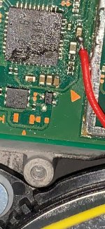
did i break the GND point on my V2? I can not turn on mu switch
 

Attachments

  • DAAED707-AD0E-42C3-931E-612AAF7AD039.jpeg
    DAAED707-AD0E-42C3-931E-612AAF7AD039.jpeg
    197.5 KB · Views: 15

abal1000x

Well-Known Member
Member
Joined
Jun 5, 2022
Messages
1,070
Trophies
0
XP
1,397
Country
Gaza Strip
did i break the GND point on my V2? I can not turn on mu switch
Theres lot of GND point, but some people prefer to solder it on some component, which not designed for it, and might broke it cause of the heat, and mechanical force.

I prefer use the GND pad, GND shield, etc, which is designed to be soldered. Especially the GND pad that big and have lot of vias on it to the bottom layer. Its so strong that it could hold high mechanical force.
 
  • Like
Reactions: Browbon

Site & Scene News

Popular threads in this forum

General chit-chat
Help Users
  • No one is chatting at the moment.
    OctoAori20 @ OctoAori20: Welp