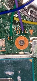
Inspect with camera zoom .. also post the pic on the point you suspect (you must have right?). Let us see that.did i break the GND point on my V2? I can not turn on mu switch
You are using an out of date browser. It may not display this or other websites correctly.
You should upgrade or use an alternative browser.
You should upgrade or use an alternative browser.
Staff Posts
Recent threadmarks
sharing files
Important Posts
Recent threadmarks
Firmwaresthis GND point, i try to turn on my switch without applying mod but it can not. My Switch is V2Inspect with camera zoom .. also post the pic on the point you suspect (you must have right?). Let us see that.
Post automatically merged:
did my point break? i can not see the metal part compare with the next oneTheres lot of GND point, but some people prefer to solder it on some component, which not designed for it, and might broke it cause of the heat, and mechanical force.
I prefer use the GND pad, GND shield, etc, which is designed to be soldered. Especially the GND pad that big and have lot of vias on it to the bottom layer. Its so strong that it could hold high mechanical force.
Attachments
lmao...You can try play Mariokart8, if it doesnt crash then its fine.
monster hunter rise also pretty


 for me...
my lite become a Hot Pack
this GND point, i try to turn on my switch without applying mod but it can not. My Switch is V2
Post automatically merged:
did my point break? i can not see the metal part compare with the next one
Looking from https://balika011.hu/switch/erista, it seems similar.
Try to check the cap using multimeter, about the connectivity to the ic pin. Or try measure the cap value (ic chip pin and ground).
Logically the capacitor still works, usually the ripped part is only the top and some of the side, but the bottom still intact.
I doubt that this cap is the reason v2 is not turn on.
Can you elaborate about how can you know that the v2 is not turn on?
Is the backlight on but nothing shows up. Or when powering up, nothins shows, not even a backlight.
sadly i dont have any kind of multi meter to check the value. I try to hold the start button but the switch dont show anything, even the blacklightView attachment 377417
Looking from https://balika011.hu/switch/erista, it seems similar.
Try to check the cap using multimeter, about the connectivity to the ic pin. Or try measure the cap value (ic chip pin and ground).
Logically the capacitor still works, usually the ripped part is only the top and some of the side, but the bottom still intact.
I doubt that this cap is the reason v2 is not turn on.
Can you elaborate about how can you know that the v2 is not turn on?
Is the backlight on but nothing shows up. Or when powering up, nothins shows, not even a backlight.
That cap is likely gone. It's not just that top pad is missing but it's also tilted to the side so the bottom pad might be damaged aswell.sadly i dont have any kind of multi meter to check the value. I try to hold the start button but the switch dont show anything, even the blacklight
But, as abal1000x said, I don't think this should be a reason the switch is not turning on.
I would remove that cap and see what happens.
Also, post pictures of other solder points so we can see if the problem is somewhere else.
Here is my point. Also i got a weird RST point with one part in the right. It make me hard to solder that point
And sr for poor quality pics, i dont have microscope. The best i can have is my phone with some microscope app
That cap is likely gone. It's not just that top pad is missing but it's also tilted to the side so the bottom pad might be damaged aswell.
But, as abal1000x said, I don't think this should be a reason the switch is not turning on.
I would remove that cap and see what happens.
Also, post pictures of other solder points so we can see if the problem is somewhere else.
Post automatically merged:
And sr for poor quality pics, i dont have microscope. The best i can have is my phone with some microscope app
Attachments
for better picture try to go on well lit room or outside.. and dont use camera flash. please take another picture so the details can be seenHere is my point. Also i got a weird RST point with one part in the right. It make me hard to solder that point
Post automatically merged:
And sr for poor quality pics, i dont have microscope. The best i can have is my phone with some microscope app
Well not really its pretty easy I would say , haven't done a lot of hardware mods though think the last one I done was Of Xbox alladine xt chip so.ِExactly. Do you consider Picofly the toughest mod you've ever done?
Phone repair is a lot harder I would say
Post automatically merged:
That cap is def destroyeddid i break the GND point on my V2? I can not turn on mu switch
for better picture try to go on well lit room or outside.. and dont use camera flash. please take another picture so the details can be seen
That cap is likely gone. It's not just that top pad is missing but it's also tilted to the side so the bottom pad might be damaged aswell.
But, as abal1000x said, I don't think this should be a reason the switch is not turning on.
I would remove that cap and see what happens.
Also, post pictures of other solder points so we can see if the problem is somewhere else.
for god shake, sr for my dumb brain. I forgot to put emmc part in my V2, i thought it solder in mobo like my old litea and put it away. The switch is turn on. Thank you for all the help, I am appreciate it.View attachment 377417
Looking from https://balika011.hu/switch/erista, it seems similar.
Try to check the cap using multimeter, about the connectivity to the ic pin. Or try measure the cap value (ic chip pin and ground).
Logically the capacitor still works, usually the ripped part is only the top and some of the side, but the bottom still intact.
I doubt that this cap is the reason v2 is not turn on.
Can you elaborate about how can you know that the v2 is not turn on?
Is the backlight on but nothing shows up. Or when powering up, nothins shows, not even a backlight.
That blue cable solder point is really close to the other pad wouldn't surprise me if ur bridging hard to tell thoughHere is my point. Also i got a weird RST point with one part in the right. It make me hard to solder that point
Post automatically merged:
And sr for poor quality pics, i dont have microscope. The best i can have is my phone with some microscope app
Well, finally I replaced the burned resistor on CMD point (4K7 ohms) and the switch came back to life. But now the situation is that the RP2040 starts with blue led (glitching) and after two seconds I have the error code:
*=* (No eMMC block 0 read (eMMC init failure?)
I don´t know where to continue, I checked all the cables and the only thing I doubt is the Dat0 adapter...
Any recommendation or clue about that error code?
Thanks
*=* (No eMMC block 0 read (eMMC init failure?)
I don´t know where to continue, I checked all the cables and the only thing I doubt is the Dat0 adapter...
Any recommendation or clue about that error code?
Thanks
That blue cable solder point is really close to the other pad wouldn't surprise me if ur bridging hard to tell though
it's really the hardest point i ever solderThat blue cable solder point is really close to the other pad wouldn't surprise me if ur bridging hard to tell though
Just to make sure, what resistance did you use to replace the 4k7 ohms?Well, finally I replaced the burned resistor on CMD point (4K7 ohms) and the switch came back to life. But now the situation is that the RP2040 starts with blue led (glitching) and after two seconds I have the error code:
*=* (No eMMC block 0 read (eMMC init failure?)
I don´t know where to continue, I checked all the cables and the only thing I doubt is the Dat0 adapter...
Any recommendation or clue about that error code?
Thanks
nvm i assume that is the 4k7 on main board.
I used a 4k7 ohms 0201 1% resistor, after soldering I checked the value with the multimeter and it gave ~4k7. But later I will check again...Just to make sure, what resistance did you use to replace the 4k7 ohms?
nvm i assume that is the 4k7 on main board.
the resistor should be ok now. remove the dat0 cable from pico and lets see what error code you getWell, finally I replaced the burned resistor on CMD point (4K7 ohms) and the switch came back to life. But now the situation is that the RP2040 starts with blue led (glitching) and after two seconds I have the error code:
*=* (No eMMC block 0 read (eMMC init failure?)
I don´t know where to continue, I checked all the cables and the only thing I doubt is the Dat0 adapter...
Any recommendation or clue about that error code?
Thanks
I have made dozens of Lites without any problem, thanks again rehius for your great workI don't know what's this thing circulating about Picofly having compatibility issues with Lite. I just did three in a row all worked fine.
Following standards, using a score, and checking values have worked great for me.
just curious anyone have any issue of slightly warm switch after picofly instal ? 41-44 Celcius idle and about 47-50 while playing example zelda (FYI this is one of the first v1 i modded, and i did cut the shield abit to fit pico firstime ), also this unit have battery drain problem i just noticed recently 1-1.5 hour from full, im not sure if the unit have battery+heat problem before modding or after, any thougts on this? im still waiting the switch to arrive to confirm anything need to open it again to make sure/
Last edited by blackheartme,
Never had this issue and I cut the shield in all models except Lite.just curious anyone have any issue of slightly warm switch after picofly instal ? 41-44 Celcius idle and about 47-50 while playing example zelda (FYI this is one of the first v1 i modded, and i did cut the shield abit to fit pico firstime ), also this unit have battery drain problem i just noticed recently 1-1.5 hour from full, im not sure if the unit have battery+heat problem before modding or after, any thougts on this?
Maybe it is a preexisting condition or maybe you missed one of 3 layers of thermal paste
Yesterday I did several installations.
Among these is a dispute that I don't know how it works (after replacing the display) despite the bent mainboard.
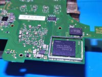
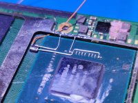
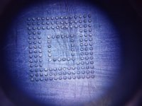
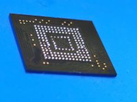
There is also an oled made with Reballing, if it can serve for some ideas, I also used new connections for the mosfet.
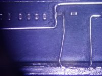
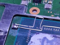
Photo release (The photos are mixed up).
I'm continuing to use FW 2.67 which in my opinion is fast, stable, reliable. What am I getting into by not using the new FW?
Now I don't get slow memory error anymore, and in emummc everything works, even waking up.
I can't get into OFW though, after the black screen nintendo logo.
What guides can I follow?
I can download the keys without error, it takes like 190 or so.
Among these is a dispute that I don't know how it works (after replacing the display) despite the bent mainboard.
There is also an oled made with Reballing, if it can serve for some ideas, I also used new connections for the mosfet.
Photo release (The photos are mixed up).
I'm continuing to use FW 2.67 which in my opinion is fast, stable, reliable. What am I getting into by not using the new FW?
Post automatically merged:
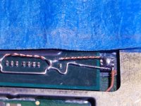
As for this problem, I carried out the unbrick level 1 and 2 procedures, after adding resistors (actually I redid the whole installation (the one carried out by the customer independently was disastrous by my standards).Hi guys, today I received a switch victim of an incorrect picofly DIY installation.
I immediately identified the problem (it was very evident) as the CPU cable was shorted to ground.
The console did not turn on.
I just partially got it working again.
The current conditions are as follows:
1) The console can start hekate but it doesn't start in OFW, Nintendo appears and then black screen. To start hekate again, I have to disconnect the battery.
2) I get slow emmc error, but I think it's an EMMC hardware error, as I can backup boot0,1 and also all emmc. However, I cannot save the keys, I receive an error (photo attached).
3) I created emummc and it starts up, but it doesn't wake up from rest mode.
My question is is there any way to reset mmc? (I have a donor switch, in case I could use the mmc.)
Can I wake from sleep in emummc?
I attach all the photos.
Thanks for your support.
Now I don't get slow memory error anymore, and in emummc everything works, even waking up.
I can't get into OFW though, after the black screen nintendo logo.
What guides can I follow?
I can download the keys without error, it takes like 190 or so.
Attachments
-
 WhatsApp Image 2023-06-12 at 10.19.40 (1).jpeg290.9 KB · Views: 23
 -
 WhatsApp Image 2023-06-12 at 10.19.39.jpeg232 KB · Views: 20
 -
 WhatsApp Image 2023-06-12 at 10.19.39 (4).jpeg258.6 KB · Views: 17
 -
 WhatsApp Image 2023-06-12 at 10.19.39 (3).jpeg202.2 KB · Views: 22
 -
 WhatsApp Image 2023-06-12 at 10.19.39 (2).jpeg243.7 KB · Views: 20
 -
 WhatsApp Image 2023-06-12 at 10.19.39 (1).jpeg257.3 KB · Views: 23
 -
 WhatsApp Image 2023-06-12 at 10.19.38.jpeg310.9 KB · Views: 22
 -
 WhatsApp Image 2023-06-12 at 10.19.38 (6).jpeg156.9 KB · Views: 21
 -
 WhatsApp Image 2023-06-12 at 10.19.38 (5).jpeg198.5 KB · Views: 25
 -
 WhatsApp Image 2023-06-12 at 10.19.40 (2).jpeg308.9 KB · Views: 20
 -
 WhatsApp Image 2023-06-12 at 10.19.40 (3).jpeg359.4 KB · Views: 19
 -
 WhatsApp Image 2023-06-12 at 10.19.41.jpeg180.3 KB · Views: 18
 -
 WhatsApp Image 2023-06-12 at 10.19.41 (3).jpeg182.6 KB · Views: 18
 -
 WhatsApp Image 2023-06-12 at 10.19.41 (2).jpeg215.6 KB · Views: 21
 -
 WhatsApp Image 2023-06-12 at 10.19.41 (1).jpeg209.3 KB · Views: 19
 -
 WhatsApp Image 2023-06-12 at 10.19.40.jpeg302.2 KB · Views: 22
 -
 WhatsApp Image 2023-06-12 at 10.19.40 (7).jpeg171 KB · Views: 19
 -
 WhatsApp Image 2023-06-12 at 10.19.40 (6).jpeg291.9 KB · Views: 20
 -
 WhatsApp Image 2023-06-12 at 10.19.40 (5).jpeg284.3 KB · Views: 23
 -
 WhatsApp Image 2023-06-12 at 10.19.40 (4).jpeg318 KB · Views: 21
 -
 WhatsApp Image 2023-06-12 at 10.19.38 (4).jpeg271.4 KB · Views: 20
 -
 WhatsApp Image 2023-06-12 at 10.19.38 (3).jpeg153.4 KB · Views: 17
 -
 WhatsApp Image 2023-06-12 at 10.19.38 (2).jpeg85 KB · Views: 21
 -
 WhatsApp Image 2023-06-12 at 10.19.35 (7).jpeg337.8 KB · Views: 16
 -
 WhatsApp Image 2023-06-12 at 10.19.35 (6).jpeg250.2 KB · Views: 21
 -
 WhatsApp Image 2023-06-12 at 10.19.35 (2).jpeg275.7 KB · Views: 18
 -
 WhatsApp Image 2023-06-12 at 10.19.35 (1).jpeg287.2 KB · Views: 18
 -
 WhatsApp Image 2023-06-12 at 10.19.34.jpeg438 KB · Views: 18
 -
 WhatsApp Image 2023-06-12 at 10.19.34 (4).jpeg296.2 KB · Views: 20
 -
 WhatsApp Image 2023-06-12 at 10.19.34 (3).jpeg376 KB · Views: 22
 -
 WhatsApp Image 2023-06-12 at 10.19.34 (2).jpeg419.2 KB · Views: 24
 -
 WhatsApp Image 2023-06-12 at 10.19.33.jpeg255.6 KB · Views: 21
 -
 WhatsApp Image 2023-06-12 at 10.19.35.jpeg268 KB · Views: 16
 -
 WhatsApp Image 2023-06-12 at 10.19.36 (1).jpeg225.5 KB · Views: 17
 -
 WhatsApp Image 2023-06-12 at 10.19.38 (1).jpeg90.5 KB · Views: 18
 -
 WhatsApp Image 2023-06-12 at 10.19.37.jpeg217 KB · Views: 16
 -
 WhatsApp Image 2023-06-12 at 10.19.37 (6).jpeg131 KB · Views: 17
 -
 WhatsApp Image 2023-06-12 at 10.19.37 (5).jpeg118.6 KB · Views: 15
 -
 WhatsApp Image 2023-06-12 at 10.19.37 (1).jpeg128.9 KB · Views: 15
 -
 WhatsApp Image 2023-06-12 at 10.19.36.jpeg280.6 KB · Views: 17
 -
 WhatsApp Image 2023-06-12 at 10.19.36 (5).jpeg196.6 KB · Views: 15
 -
 WhatsApp Image 2023-06-12 at 10.19.36 (3).jpeg186.4 KB · Views: 20
 -
 WhatsApp Image 2023-06-12 at 10.19.36 (2).jpeg368.7 KB · Views: 16
 -
 WhatsApp Image 2023-06-12 at 13.12.39.jpeg268.8 KB · Views: 19
Last edited by cicci084,
Similar threads
- Replies
- 5
- Views
- 3K
- Replies
- 2
- Views
- 900
- Replies
- 42
- Views
- 7K
Site & Scene News
New Hot Discussed
-
-
20K views
Majora’s Mask PC port 2Ship2Harkinian gets its first release
After several months of work, the Harbour Masters 64 team have released their first public build of 2Ship2Harkinian, a feature-rich Majora's Mask PC port. This comes... -
19K views
Mario Builder 64 is the N64's answer to Super Mario Maker
With the vast success of Super Mario Maker and its Switch sequel Super Mario Maker 2, Nintendo fans have long been calling for "Maker" titles for other iconic genres... -
18K views
Modders hint at potential kernel exploit hack for Xbox One consoles
It's been a while since Microsoft released the Xbox One, and despite its age, there haven't been any reliable softmod methods to hack the console. Until now. A post... -
17K views
The founder of Oculus is releasing a $199 FPGA Game Boy system
Palmer Luckey is known for his pursuits into the world of virtual reality, having founded Oculus and designed the Rift VR headset. Prior to the $2 billion dollar... -
14K views
Nintendo takes down the Breath of the Wild randomizer mod from Gamebanana
Another day, another Nintendo DMCA takedown against fan-made content. Just a few minutes ago, Nintendo issued a DMCA takedown notice against a widely known and...by ShadowOne333 104 -
14K views
The Kingdom Hearts games are coming to Steam
After a little more than three years of exclusivity with the Epic Games Store, Square Enix has decided to bring their beloved Kingdom Hearts franchise to Steam. The... -
12K views
Select PlayStation 2 games are coming to PlayStation 5
Sony is once more attempting to reintroduce players to their older library of games by re-releasing classic PlayStation 2 titles onto the PlayStation Store. During... -
11K views
Skyward Sword HD randomizer announced with release date and trailer
Skyward Sword is a divisive title in the Zelda series. Hailed with praise at launch with a 93 Metacritic average, the game since received criticism for the... -
10K views
PlayStation State of Play May 2024 showcase - God of War: Ragnarok coming to PC
The latest State of Play is here. This is PlayStation's Summer showcase, providing updates to new updates on upcoming games and brand new reveals. The 35-minute... -
9K views
Nintendo acquires company behind Mortal Kombat 1 and Hogwarts Legacy ports on Switch, "Shiver Entertainment Inc."
Nintendo is having quite the successful console generation with the Nintendo Switch, and with the follow-up to the Switch already on the horizon confirmed by...by ShadowOne333 48
-
-
-
169 replies
The founder of Oculus is releasing a $199 FPGA Game Boy system
Palmer Luckey is known for his pursuits into the world of virtual reality, having founded Oculus and designed the Rift VR headset. Prior to the $2 billion dollar...by Chary -
118 replies
Modders hint at potential kernel exploit hack for Xbox One consoles
It's been a while since Microsoft released the Xbox One, and despite its age, there haven't been any reliable softmod methods to hack the console. Until now. A post...by Chary -
108 replies
Majora’s Mask PC port 2Ship2Harkinian gets its first release
After several months of work, the Harbour Masters 64 team have released their first public build of 2Ship2Harkinian, a feature-rich Majora's Mask PC port. This comes...by Scarlet -
104 replies
Nintendo takes down the Breath of the Wild randomizer mod from Gamebanana
Another day, another Nintendo DMCA takedown against fan-made content. Just a few minutes ago, Nintendo issued a DMCA takedown notice against a widely known and...by ShadowOne333 -
91 replies
The Kingdom Hearts games are coming to Steam
After a little more than three years of exclusivity with the Epic Games Store, Square Enix has decided to bring their beloved Kingdom Hearts franchise to Steam. The...by Chary -
79 replies
Select PlayStation 2 games are coming to PlayStation 5
Sony is once more attempting to reintroduce players to their older library of games by re-releasing classic PlayStation 2 titles onto the PlayStation Store. During...by Chary -
66 replies
Mario Builder 64 is the N64's answer to Super Mario Maker
With the vast success of Super Mario Maker and its Switch sequel Super Mario Maker 2, Nintendo fans have long been calling for "Maker" titles for other iconic genres...by Scarlet -
64 replies
PlayStation State of Play May 2024 showcase - God of War: Ragnarok coming to PC
The latest State of Play is here. This is PlayStation's Summer showcase, providing updates to new updates on upcoming games and brand new reveals. The 35-minute...by Chary -
62 replies
Summer Game Fest 2024 coverage - Civilization VII announced
E3 may be gone, but it's not forgotten, as the trend of a massive Summer video game showcase still lives on in the form of the Summer Game Fest. Promising two hour of...by Chary -
55 replies
Doom for SNES full source code released by former Sculptured Software employees
The complete source code for the Super Nintendo Entertainment System (SNES) version of Doom has been released on archive.org. Although some of the code was partially...by shaunj66
-
Popular threads in this forum
General chit-chat
-
 Xdqwerty
Loading…what are you looking at?
 -
 BakerMan
Loading…I rather enjoy a life of taking it easy. I haven't reached that life yet though.
-
-
-
-
-
-
-
-
-
-
-
 @
Xdqwerty:
Also, do songs that werent made for a videogame but do appear in a videogame count as game songs @SylverReZ?+1
 -
-
-
-
-
-
-
-
-
-
-
 @
Xdqwerty:
@SylverReZ, the first one is a dnb song i put and the second one is a song that became popular due to gd that i really like
@
Xdqwerty:
@SylverReZ, the first one is a dnb song i put and the second one is a song that became popular due to gd that i really like -
 @
BakerMan:
i would say if it's not for a video game but it's in a video game, it counts if it's not a music game+1
so it counts for hotline miami and geometry dash, but not just dance or beat saber -
-


